Multilayer three-dimensional rotational flow sieve plate and multilayer rotational flow sieve plate tower

A multi-layer, flow sieve plate technology, applied in the direction of using liquid separation agent, distillation separation, dispersion particle separation, etc., can solve the problems of high production cost, high energy consumption, low mass transfer efficiency, etc., and achieve excellent anti-blocking performance , high mass transfer efficiency, enhanced mass transfer and heat transfer effects

Active Publication Date: 2017-02-08
HEBEI UNIV OF TECH
View PDF5 Cites 3 Cited by
  • Summary
  • Abstract
  • Description
  • Claims
  • Application Information

AI Technical Summary

Problems solved by technology

[0006] The purpose of the present invention is to provide a multi-layer three-dimensional swirling sieve plate and a multi-layer swirling sieve plate tower to solve the problems of low mass transfer efficiency, high energy consumption and high production cost

Method used


Image

  • Multilayer three-dimensional rotational flow sieve plate and multilayer rotational flow sieve plate tower
  • Multilayer three-dimensional rotational flow sieve plate and multilayer rotational flow sieve plate tower
  • Multilayer three-dimensional rotational flow sieve plate and multilayer rotational flow sieve plate tower

Examples


Embodiment Construction

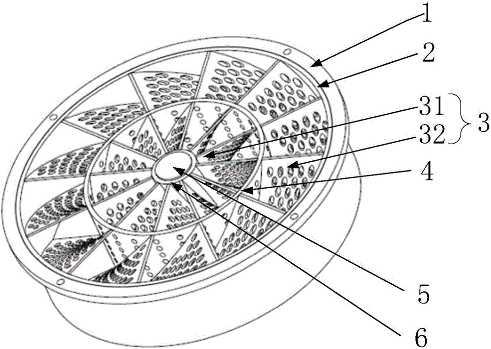
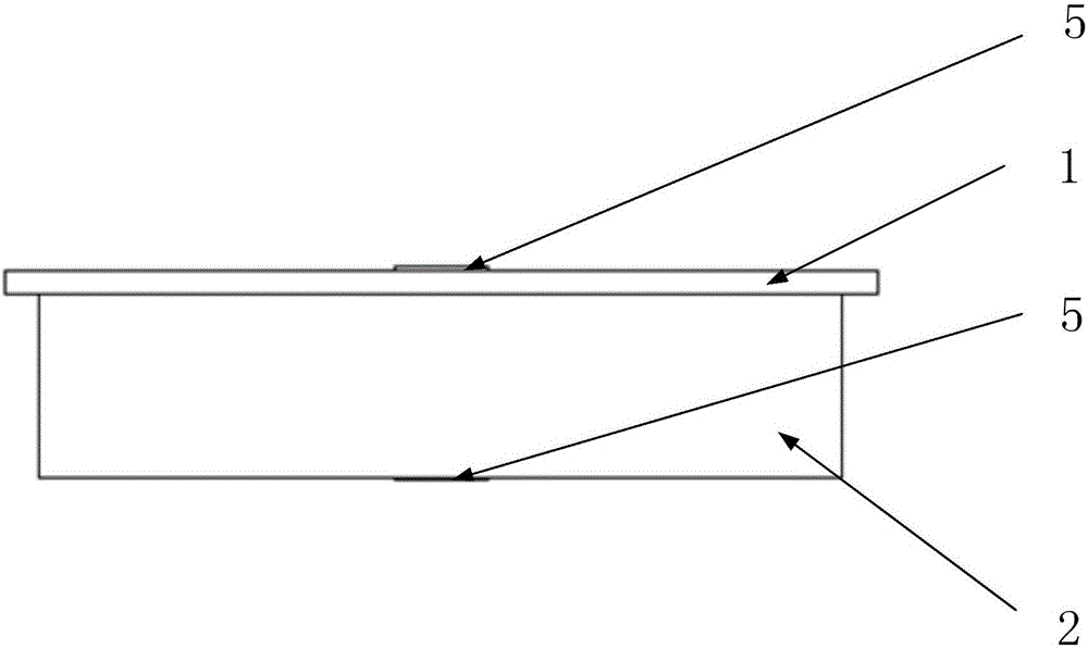
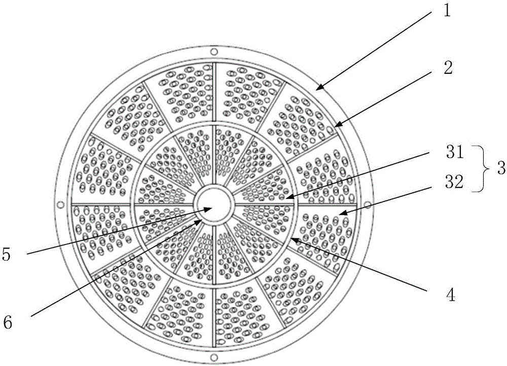
[0032] The technical solutions of the present invention will be clearly and completely described below in conjunction with the accompanying drawings. Apparently, the described embodiments are some of the embodiments of the present invention, but not all of them. Based on the embodiments of the present invention, all other embodiments obtained by persons of ordinary skill in the art without making creative efforts belong to the protection scope of the present invention.

[0033] In the description of the present invention, it should be noted that the terms "center", "upper", "lower", "left", "right", "vertical", "horizontal", "inner", "outer" etc. The indicated orientation or positional relationship is based on the orientation or positional relationship shown in the drawings, and is only for the convenience of describing the present invention and simplifying the description, rather than indicating or implying that the referred device or element must have a specific orientation, ...


PUM

PropertyMeasurementUnit
diameteraaaaaaaaaa
porosityaaaaaaaaaa

Abstract

The invention provides a multilayer three-dimensional rotational flow sieve plate and a multilayer rotational flow sieve plate tower, and relates to the technical field of tower equipment. The multilayer three-dimensional rotational flow sieve plate comprises an inner tube, a middle tube, an outer tube and a rotational flow sieve plate, wherein the inner tube, the middle tube and the outer tube are sequentially arranged together from inside to outside in a sleeving way; the rotational flow sieve plate comprises an inner rotational flow sieve plate and an outer rotational flow sieve plate; the inner tube and the middle tube are connected through the inner rotational flow sieve plate; the middle tube and the outer tube are connected through an outer rotational flow sieve plate; holes are formed in the rotational flow sieve plate. The multilayer three-dimensional rotational flow sieve plate has the advantages that when the multilayer three-dimensional rotational flow sieve plates are combined, the mass transfer efficiency of the multilayer three-dimensional rotational flow sieve plate is high. Compared with other kinds of tower plates, the multilayer three-dimensional rotational flow sieve plate has the beneficial effects that on the premise of reaching the identical mass transfer effect, the installation quantity of the tower plate can be reduced; the press drop is low; the energy consumption of a water pump, a fan and the like can be effectively reduced; the flux of the multilayer three-dimensional rotational flow sieve plate is greater; the multilayer three-dimensional rotational flow sieve plate can adapt to the selection of larger tower diameter adsorption tower; the mechanical intensity is stable; safety and reliability are realized; the anti-blockage performance is excellent; the obvious advantage is realized in an aspect of dust containing gas treatment.

Description

technical field [0001] The invention relates to the technical field of tower equipment, in particular to a multi-layer three-dimensional swirl sieve plate and a multi-layer swirl sieve plate tower. Background technique [0002] Tower equipment is widely used in chemical, petrochemical and other production industries, mainly for unit operations such as rectification, absorption, desorption, gas humidification and cooling. According to the different forms of internal components, tower equipment is often divided into two categories: plate tower and packed tower. Compared with packed tower, plate tower has the advantages of large processing capacity, low resistance energy consumption, excellent anti-blocking performance, and low cost. [0003] The tray is the core component of the plate tower equipment, and it is the main place where the gas (steam) liquid or liquid-liquid two phases are fully contacted, so as to achieve the purpose of heat transfer and mass transfer between the...

Claims


Application Information

Patent Timeline
Patent Type & Authority Applications(China)
IPC IPC(8): B01D3/26B01D53/18B01D47/00
CPCB01D3/26B01D47/00B01D53/18
Inventor 刘琛王晋刚唐猛张少峰王丽瑶王璐莎
Owner HEBEI UNIV OF TECH
Why Eureka
Try Eureka