Biomass pyrolysis liquefying systems

A biomass and carrier technology, applied in the field of biomass cracking and liquefaction systems, can solve the problems of affecting the efficiency of biomass pyrolysis and liquefaction of heat sources, low calorific value of non-condensable gases, and inability to fully mix, so as to achieve low overall cost, The effect of low processing technology requirements and excellent work performance

Inactive Publication Date: 2004-04-21
SHANDONG UNIV OF TECH
View PDF0 Cites 15 Cited by
  • Summary
  • Abstract
  • Description
  • Claims
  • Application Information

AI Technical Summary

Problems solved by technology

At present, several types of equipment are available to complete this process, such as the carried-bed reactor developed by GIT of Georgia Institute of Technology in the United States, and the rotating cone-shell reactor developed by Choate University in the Netherlands. Combustion is introduced into the lower combustion zone of the reaction tube. The hot flue gas passes through the reaction tube from bottom to top and mixes with the biomass behind the inlet to heat the biomass. Generally, the flow rate of the hot flue gas should be 4% of the flow rate of the biomass. times, the disadvantage is: a large amount of hot flue gas is required as a carrier gas during operation, and the calorific value of the non-condensable gas is low; the latter has a high oil production rate and does not require a carrier gas during operation, but the energy consumption of the whole device is high
This device does not require an inert carrier gas, the equipment structure and operating conditions are relatively simple, and the energy consumption is low. The defects are: 1. But it does not involve the heating of the heat carrier and the recovery of the combustible gas produced in the liquefaction process, and the heating of biomass The energy recovery of the post-heat heat carrier, the total cost of biomass liquefaction needs to be reduced, and the utilization rate of energy and the continuity of biomass pyrolysis and liquefaction need to be further improved; 2. The reaction tube is vertical and linear, and the heat carrier The residence time of biomass in it is short, the pyrolysis time of biomass in the reaction tube is short at the same height, and it cannot be fully mixed, which affects the utilization rate of heat source and the efficiency of pyrolysis and liquefaction of biomass. At the same time, in the pyrolysis process The thermal expansion of the middle reaction tube also has a certain destructive force on the whole biomass liquid fuel conversion system, and its working performance needs to be further improved

Method used


Image

  • Biomass pyrolysis liquefying systems
  • Biomass pyrolysis liquefying systems
  • Biomass pyrolysis liquefying systems

Examples


Embodiment Construction

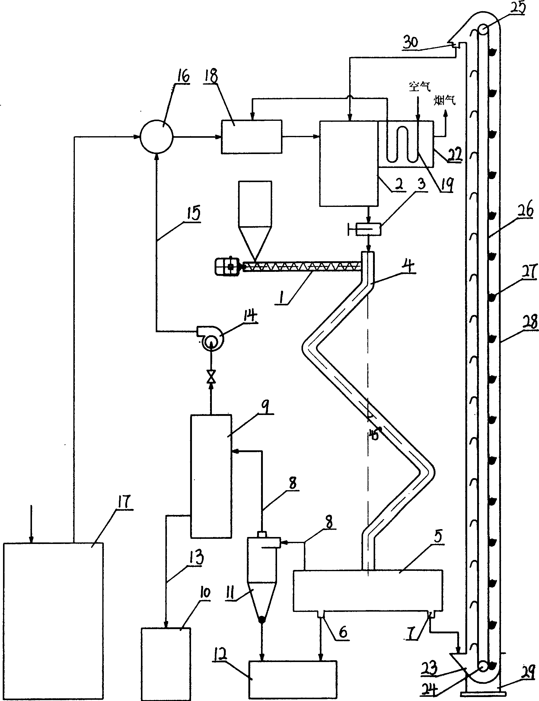
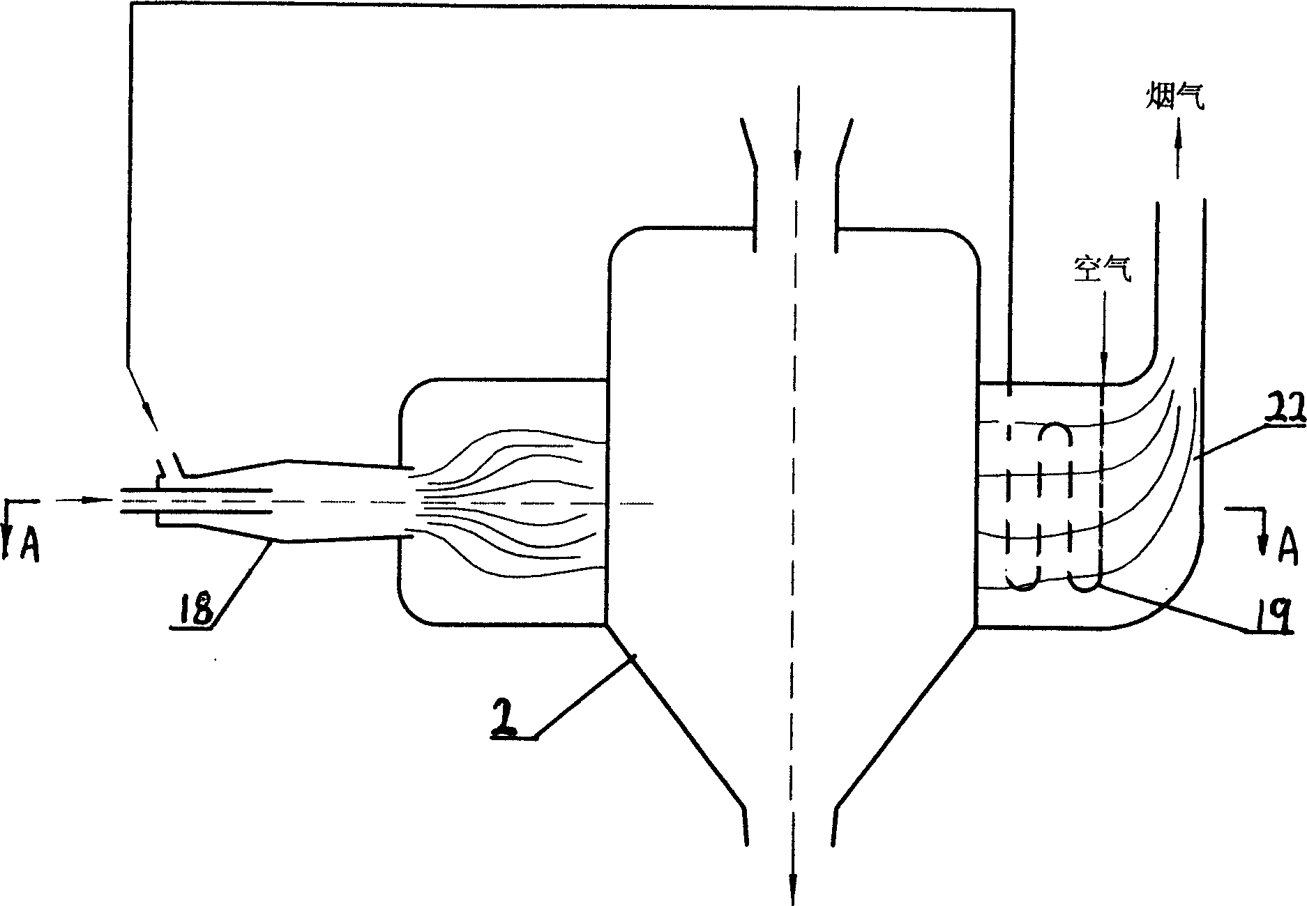
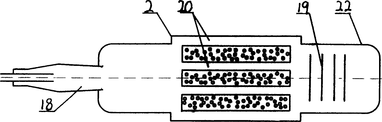
[0018] 1. Biomass feeding mechanism 2, heat carrier heating furnace 3, flow control valve 4, reaction tube 5, separation device 6, biomass residue outlet 7, heat carrier outlet 8, pyrolysis steam channel 9, shock device 10, storage Oil tank 11, cyclone dust collector 12, biomass residue collection box 13, oil outlet pipe 14, induced draft fan 15, pyrolysis gas pipeline 16, gas mixer 17, biomass gasifier 18, gas burner 19, air preheating Device 20, heating gas flue 21, hot air pipe 22, flue exhaust 23, heat carrier collection box 24, lower gear 25, upper gear 26, chain 27, hopper 28, lifting cylinder 29, base 30, outlet

[0019] Figure 1~3 In the shown embodiment: the reaction tube 4 is in a "Z" shape, and the included angle between the direction of the tube and the vertical direction is 45°. The upper end of the reaction tube 4 communicates with the outlet of the biomass feeding mechanism 1, and its top passes through The control valve 3 communicates with the outlet at the b...


PUM


Abstract

A biomass cracking and liquefying system is disclosed. The Z-shaped reaction pipe has a top end connected respectively with the feeder of biomass and the heat carrier outlet of the heat carrier heater, and a bottom end connected to the separator whose top end is connected to cooling unit and whose bottom end has residual biomass outlet and heat carrier outlet. The input of gas mixer is connected respectively to the gas outlet of biomass gasifier and the thermocomposed gas outlet of cooling unit, and its output is connected to gas burner communicated to the heater of heat carrier. It features that the combustible gas generated in gasifying and liquefying biomass is used as the energy source for thermodecomposing and liquefying, so having low cost.

Description

Technical field [0001] The invention provides a biomass cracking and liquefaction system, in particular a biomass pyrolysis and liquefaction device with a heat carrier circulation lifting device. Background technique [0002] Biomass is heated and cooled in a very short time to obtain bio-oil, charcoal and non-condensable gas. This is a process that uses fast pyrolysis to develop energy from biomass. At present, several types of equipment are available to complete this process, such as the carried-bed reactor developed by GIT of Georgia Institute of Technology in the United States, and the rotating cone-shell reactor developed by Choate University in the Netherlands. Combustion is introduced into the lower combustion zone of the reaction tube. The hot flue gas passes through the reaction tube from bottom to top and mixes with the biomass behind the inlet to heat the biomass. Generally, the flow rate of the hot flue gas should be 4% of the flow rate of the biomass. times, th...

Claims


Application Information

Patent Timeline
Patent Type & Authority Applications(China)
IPC IPC(8): C10G1/00
Inventor 易维明柏雪源何芳李永军李志合
Owner SHANDONG UNIV OF TECH
Why Eureka
Try Eureka