
Lie-down massager

Inactive Publication Date: 2005-01-13
SHIM 30 SIMON K
View PDF36 Cites 44 Cited by
  • Summary
  • Abstract
  • Description
  • Claims
  • Application Information

AI Technical Summary

Benefits of technology

[0004] The present invention is contrived to overcome the conventional disadvantages. Accordingly, an object of the invention is to provide a lie-down massager that improves therapeutic effects by adopting an air cylinder lifting mechanism for a vertical movement of massaging bumps. Another object is to stabilize the vertical movement of the massaging bumps, thereby enabling patients to receive a steady and robust massaging of the massaging bumps applied to and along their backs and necks. A further object is to improve product reliability and customer satisfaction by mechanically stabilizing the vertical movement of the massaging bumps.
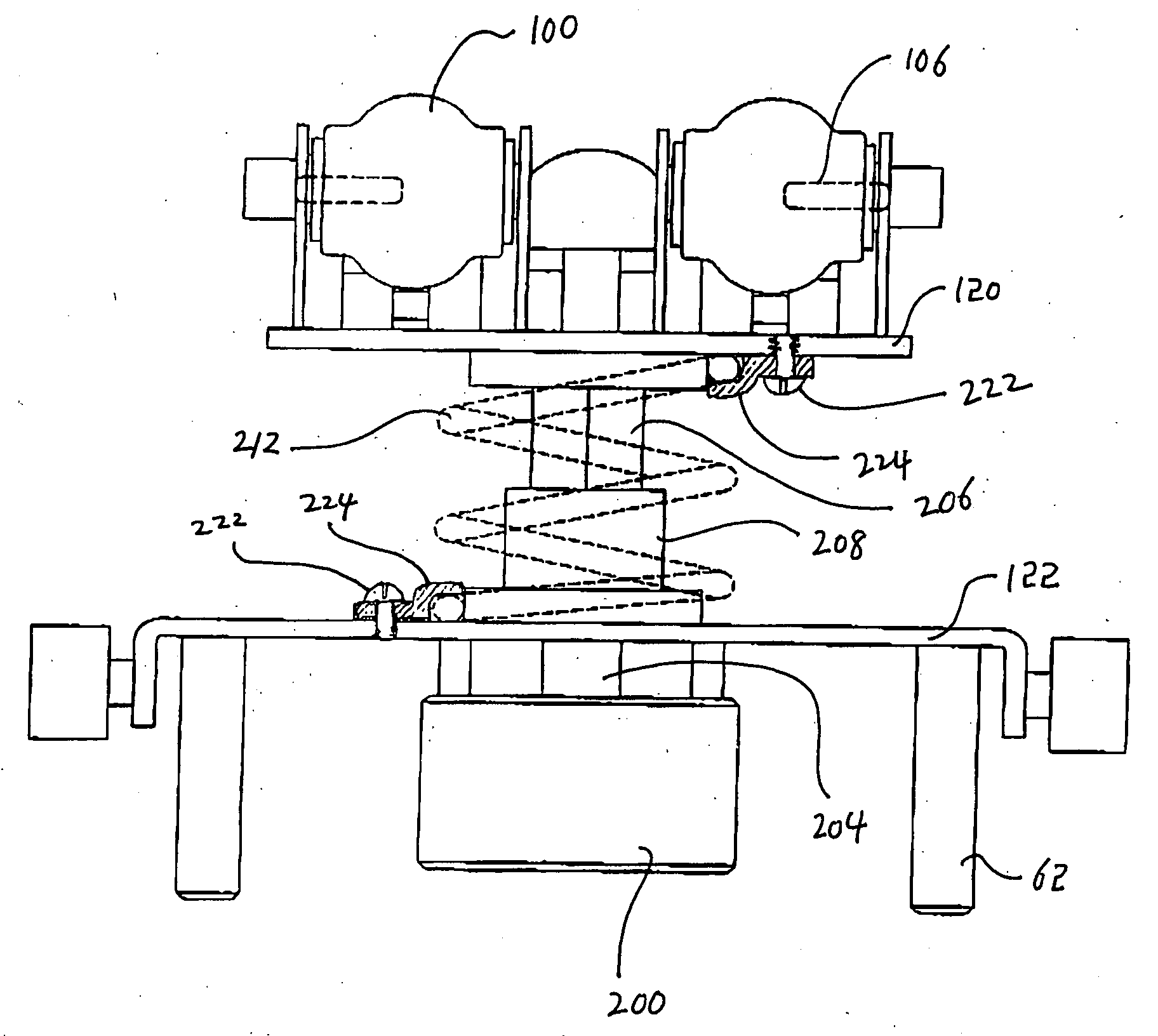
[0016] Advantages of the present inventions include that: (1) the air cylinder lifting mechanism minimizes parts required for the vertical movement of the massaging, while improving stability in the vertical reciprocation of the lifter carrying the massaging bumps; (2) the air cylinder lifting mechanism provides smooth and quite operation of the lifter; (3) the air cylinder lifting mechanism provides cushioning effect when the massage bumps are moved against a body of a patient; (4) the tension spring prevents abrupt lifting of the massage bumps and provides good controllability of the air cylinder operation; (5) the square guide shaft and the guide bearing provides guiding effect eliminating the need of separate guide members such as guide pins and guide bushes; and (5) the coasting member working with the roller coasters to realize an additional lifting by utilizing the horizontally reciprocal movement of the rider enables the massaging bumps to continue a smooth, steady and robust massaging on the patient, thereby substantially improving massaging effect and subsequently maximizing customer satisfaction.

Problems solved by technology

However, when it comes to therapeutic effects, the spring mechanism proves too soft to push up the massaging bumps when stronger pressure is required, because tension of springs applies equally to patients lying on the massaging device regardless of patient's requirements.

Method used


Image

  • Lie-down massager
  • Lie-down massager
  • Lie-down massager

Examples


Embodiment Construction

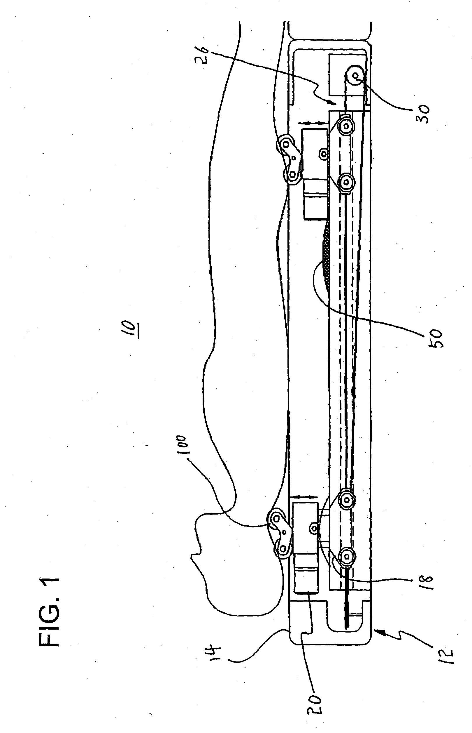
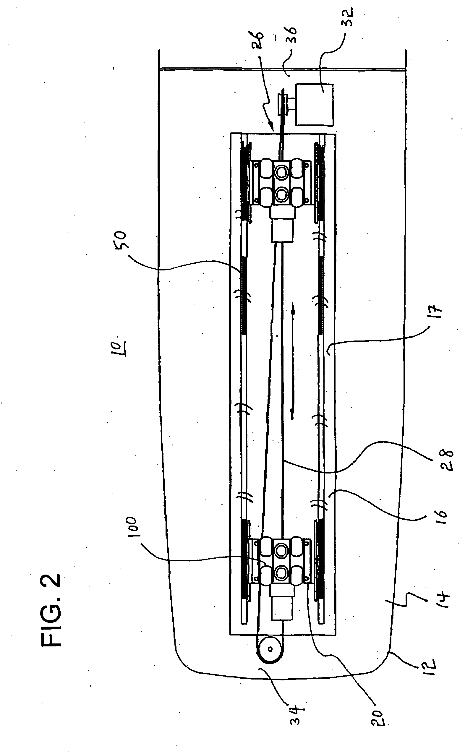
[0031]FIG. 1 shows a brief massaging mechanism of a lie-down massager 10 according to the present invention with a patient lying thereon for a bodily massage, and FIG. 2 shows a plan view of the massager 10 excluding the patient. As shown therein, the lie-down massager 10 includes a base frame 12 in a bed type or a mat type. The base frame 12 includes an elongated top panel 14, and an elongated opening 16 is formed centrally and lengthwise through the elongated top panel 14. The massager 10 includes a rider 18 and a lifter 20. The rider 18 is provided below the elongated top panel 14 of the base frame 12.

[0032] In order to implement the horizontal reciprocation of the rider 18, there is provided a guide member 26 movably engaged between the base frame 12 and the rider 18 so as to enable the rider 18 to make a horizontally reciprocal movement relative to the base frame 12. Here, it is recommended that the guide member 26 be either a rope-pulley application or a rack gear application...


PUM


Abstract

A lie-down massager includes a base frame having a top panel, a rider provided below the top panel of the base frame, a guide member movably engaged between the base frame and the rider to enable the rider to make a horizontally reciprocal movement relative to the base frame, massage bumps that move vertically along an elongated top opening of the elongated top panel of the base frame, and a lifter that holds the massage bumps and adjusts the height of the massage bumps. The lifter includes a top plate, a bottom plate, a fluid operated cylinder fixed to the bottom plate, and a spring fixed between the top plate and the bottom plate. The fluid operated cylinder has a cylinder shaft that is moved by pressurized fluid overcoming the force of the spring, and a guide shaft and a guide bearing that have a square cross section.

Description

BACKGROUND OF THE INVENTION [0001] The invention relates generally to a massaging device. More particularly, the present invention relates to an improved lie-down massager capable of efficiently treating bodily malfunctions such as back pain and gastrointestinal weakness by applying a therapeutic massaging treatment along the back and neck of a patient lying down on the massager whose massaging bumps move horizontally and vertically along the patient's spinal cord and neck while the vertical movement of the massaging bumps are actuated by a air cylinder lifting mechanism. [0002] Conventional bed or mat type massaging devices employ a spring mechanism for vertically moving massaging bumps. As disclosed U.S. Pat. No. 6,454,732, a spring mechanism allows the massaging bumps to gently move up and down. However, when it comes to therapeutic effects, the spring mechanism proves too soft to push up the massaging bumps when stronger pressure is required, because tension of springs applies e...

Claims


Application Information

Patent Timeline
IPC IPC(8): A61H7/00A61H15/00A61H15/02A61H37/00
CPCA61H7/004A61H15/02A61H2205/081A61H2201/1669A61H2203/0456A61H2015/0014
Inventor KIM, HAKJIN
Owner SHIM 30 SIMON K
Learn More