Stent

a stent and expandable technology, applied in the field of expandable stents, can solve the problems of difficult removal of metal mesh stents, risk of restenosis, and still a substantial risk of having a restenosis

Inactive Publication Date: 2005-01-13
ST JUDE MEDICAL COORDINATION CENT
View PDF15 Cites 76 Cited by
  • Summary
  • Abstract
  • Description
  • Claims
  • Application Information

AI Technical Summary

Benefits of technology

[0017] In a third embodiment, a more generalised stent, is disclosed, having a mesh structure of interconnecting parts joined together by joining parts that, when inserted into said body passage, is adapted to dissolve into smaller parts, wherein t...

Problems solved by technology

However, after the expansion, the metal mesh stents are difficult to remove since tissue in-growth occurs over time, and, in practise, the stents are normally left inside the blood vessel.
The main complication associated with the stenting of a stenosis in a blood vessel is the risk of having a restenosis, in which case a new stenosis develops at the same position as the first one, i.e. a new stenosis is growing inside the inserted stent.
Nevertheless, there is still a substantial risk of having a restenosis following the stenting of a coronary artery.
Further, when a stent is placed permanently inside a coronary artery, the continuous stress from the beating of the he...

Method used


Image

  • Stent
  • Stent
  • Stent

Examples


first embodiment

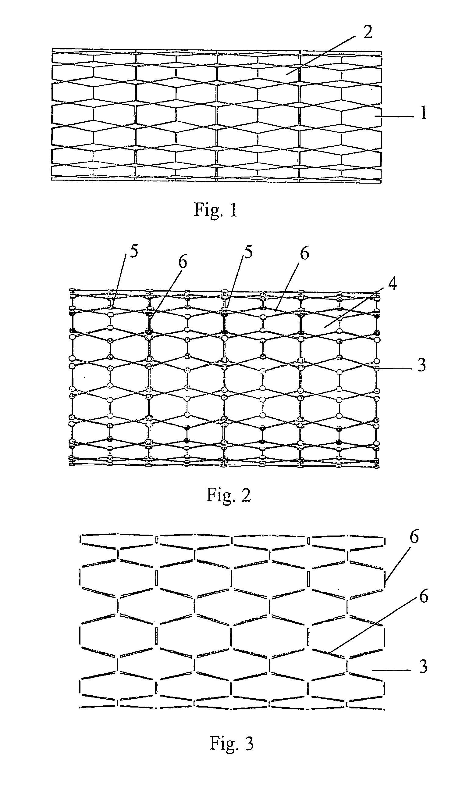
[0028]FIG. 1 illustrates an inventive stent. In FIG. 1, a stent 1 comprises a mesh 2 made of metal that corrodes in the environment prevailing inside a vessel. By choosing a suitable metal, it is possible to control the time elapsed until the stent is dissolved by corrosion inside the vessel. Obviously, this time depends on the physiological and chemical characteristics of both the vessel itself and the fluid flowing inside the vessel as well as for how long time it is necessary to support the stented vessel. A perhaps natural choice of metal would in this case be iron, or possibly an alloy of iron and a small amount of chromium or nickel in order to make the stent more resistant to corrosion, i.e. prolong the time before the stent is dissolved inside the vessel. In practise, the choice of metal or alloy may be tailored to the actual application.

second embodiment

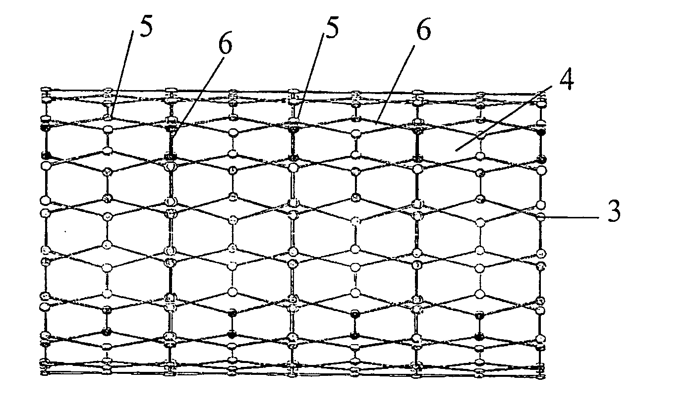
[0029] an inventive stent is illustrated in FIG. 2. Here, a stent 3 comprises a metal mesh 4, which comprises two component parts, joining 5 and interconnecting portions 6. If the joints 5 are made of metal having a lower electrochemical potential than the metal of the interconnecting portions 6, an active galvanic element is created, with the fluid inside the vessel acting as an electrolyte. This galvanic element drives an electrochemical process, in which the metal having the lower electrochemical potential is consumed, which, in this case, means that the joining portions 5 of the mesh 4 are dissolved, thereby leaving the mesh 4 in a disintegrated configuration. This disintegrated configuration is shown in FIG. 3. As is well known, the kinetics of corrosion reactions may in actual practise differ from that predicted by electrochemical potentials in standard electrochemical series. When deciding metal combinations, one must therefore also take into account the characteristics of th...

third embodiment

[0031] A more general third embodiment of the present invention is illustrated by FIGS. 2 and 3, and by FIGS. 6a-6c and 7a-7c.

[0032] By using the same reference signs, in FIGS. 6a-6c and 7a-7c, as in FIG. 2 the generalised expandable stent 3 comprises a mesh structure 4 of interconnecting portions 6 joined together by joining portions 5.

[0033] According to this third embodiment the joining portions are made from a first material and the interconnecting portions are made from a second material different from said first material, wherein the first material dissolves faster than said second material.

[0034] By using this mesh structure the stent dissolves in such a way that the longitudinal structural integrity initially is decreased and that the longitudinal structural integrity decreases faster than the radial structural integrity decreases. The radial structural integrity is related to the forces exerted by the stent towards the body passage wall. Thereby the flexibility of the st...


PUM

PropertyMeasurementUnit
Timeaaaaaaaaaa
Thicknessaaaaaaaaaa
Corrosion propertiesaaaaaaaaaa

Abstract

Expandable stent for insertion into a body passage having a mesh structure of interconnecting portions (6) joined together by joining portions (5). The stent, when inserted into said body passage, is adapted to dissolve into smaller parts, wherein the joining portions dissolve faster than the interconnecting portions. In a preferred embodiment the joining portions are made from a first material and the interconnecting portions are made from a second material different from said first material, wherein the first material dissolves faster than said second material.

Description

FIELD OF THE INVENTION [0001] The present invention relates to an expandable stent according to the preamble of the independent claim. [0002] The present invention relates generally to the field of expandable stents for insertion into vessels in the body, and particularly to dissolvable stents being made of a metal that dissolves by corrosion inside the body vessel and to disintegrating stents being made of two metals with different electrochemical potentials, thereby forming a galvanic element in which an electrochemical reaction occurs that consumes the metal having the lower electrochemical potential. BACKGROUND OF THE INVENTION [0003] A number of different stents have been proposed for the stenting of a blood vessel that has been occluded. A widely used type of stent consists of an expandable metal mesh. This type of stent may be further divided into self-expanding stents and non-self-expanding stents. [0004] The self-expanding stents can be made of a mesh material that changes ...

Claims


Application Information

Patent Timeline
IPC IPC(8): A61F2/84A61F2/00A61F2/02A61F2/06A61F2/90
CPCA61F2/91A61F2/915A61F2002/91541A61F2230/0054A61F2002/91558A61F2210/0004A61F2250/003A61F2002/9155
Inventor TENERZ, LARSVON MALMBORG, PARMATHISEN, TORBJORN
Owner ST JUDE MEDICAL COORDINATION CENT
Why Eureka
Try Eureka