

Electrochromic device having a current-reducing additive
a technology of additives and electrochromic devices, applied in the direction of organic conductors, conductive materials, instruments, etc., can solve the problems of large heat generation of electrochromic devices, large number of high operating currents of many electrochromic devices. achieve the effect of low viscosity and facilitate acceptable production rates
- Summary
- Abstract
- Description
- Claims
- Application Information
AI Technical Summary
Benefits of technology
Problems solved by technology
Method used
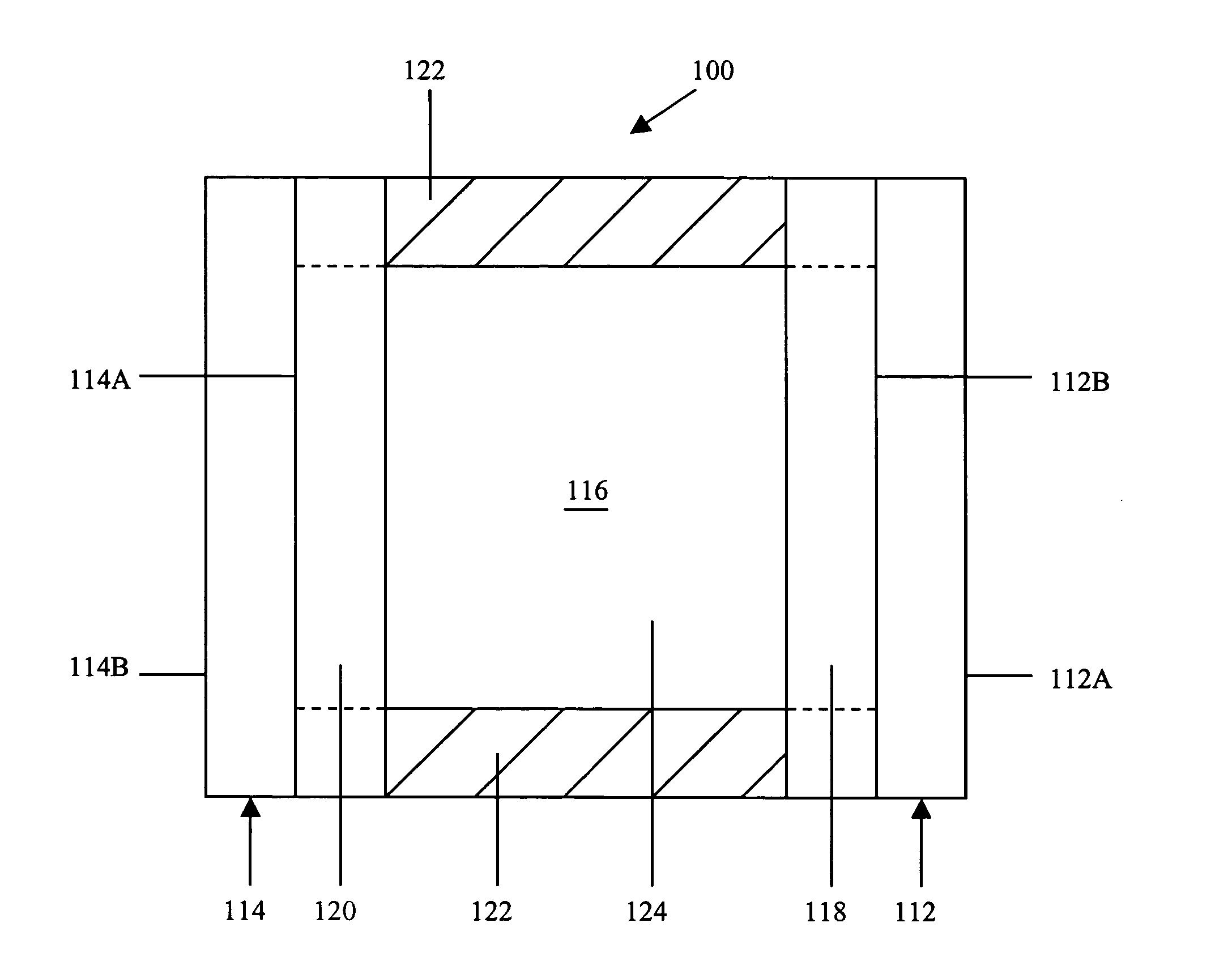
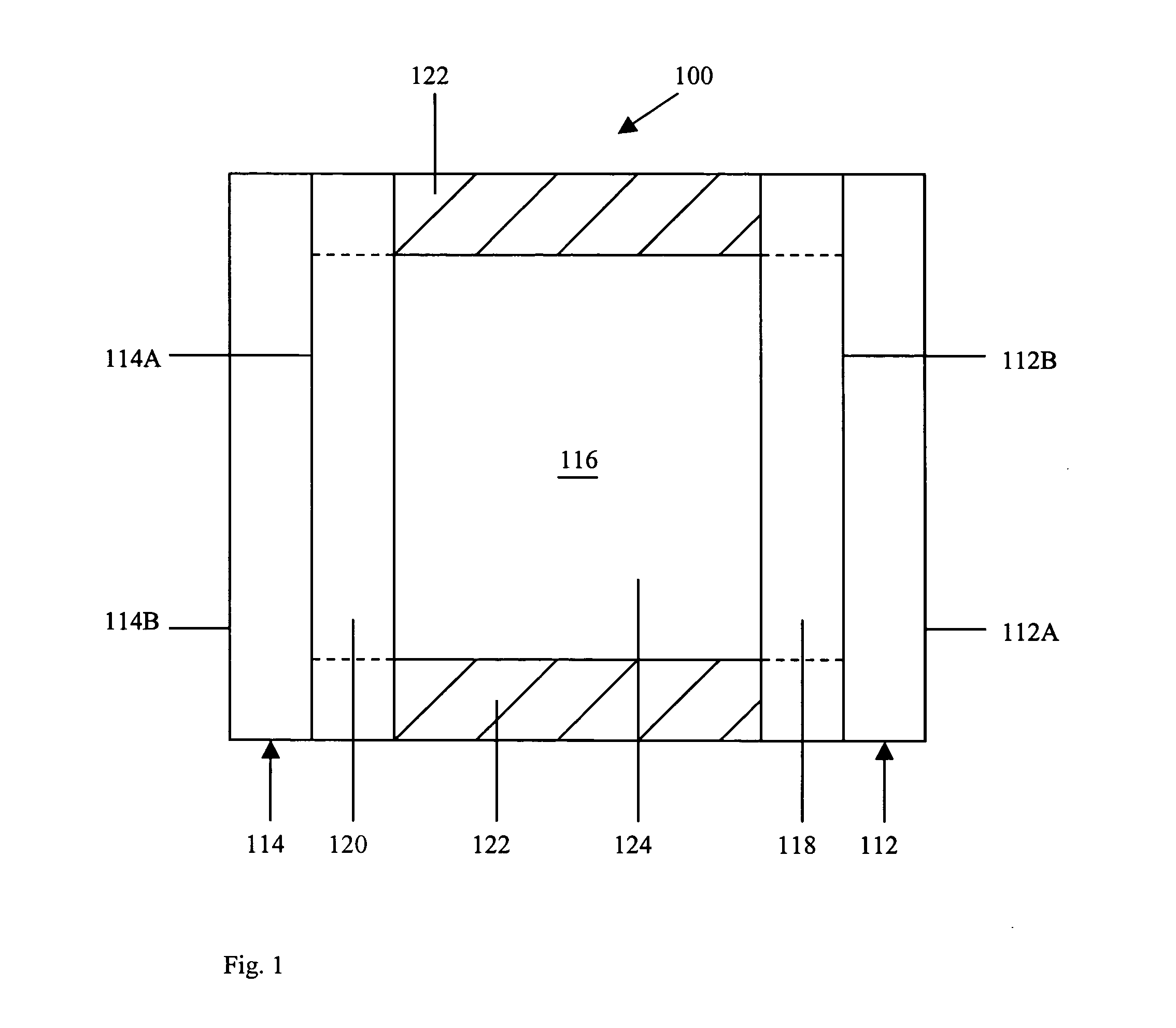
Image

Examples
first embodiment
In the present invention, the current-reducing additive may comprise at least one polymer based on polymerization of a material represented by formula I:
wherein R1-4 are the same or different and comprise H, a halide, a hydroxy group, a cyano group, an isocyano group, an isothiocyano group, a substituted or unsubstituted and straight or branched alkyl, cycloalkyl, polycycloalkyl, heterocycloalkyl, aryl, alkaryl, aralkyl, alkoxy, alkenyl, or alkynyl group containing approximately 1 to approximately 40 carbon atom(s), carbonyls, esters, carbonates, amides, ketenes, epoxides, a silyl or siloxyl group containing approximately 1 to approximately 40 silicon atom(s), and combinations thereof, wherein the average molecular weight of the current-reducing additive is greater than approximately 1,000 Daltons, and preferably ranges from approximately 1,000 to approximately 85,000 Daltons, and more preferably ranges from approximately 1,500 to approximately 50,000 Daltons.
In this embodiment, ...
second embodiment
In the present invention, the current-reducing additive may comprise at least one polymer based on polymerization of a material represented by formula II:
wherein R5-8 are the same or different and comprise H, a halide, a hydroxy group, a cyano group, an isocyano group, an isothiocyano group, a substituted or unsubstituted and straight or branched alkyl, cycloalkyl, polycycloalkyl, heterocycloalkyl, aryl, alkaryl, aralkyl, alkoxy, alkenyl, or alkynyl group containing approximately 1 to approximately 40 carbon atom(s), carbonyls, esters, carbonates, amides, ketenes, epoxides, a silyl or siloxyl group containing approximately 1 to approximately 40 silicon atom(s), and combinations thereof, wherein the average molecular weight of the current-reducing additive is greater than approximately 1,000 Daltons, and preferably ranges from approximately 1,000 to approximately 125,000 Daltons, and more preferably ranges from approximately 1,500 to approximately 50,000 Daltons.
In this embodiment...
third embodiment
In the present invention, the current-reducing additive may comprise at least one polymer represented by formula m:
wherein R9 comprises a substituted or unsubstituted and straight or branched alkyl, cycloalkyl, polycycloalkyl, heterocycloalkyl, aryl, alkaryl, aralkyl, alkoxy, alkenyl, or alkynyl group containing approximately 1 to approximately 40 carbon atom(s), carbonyls, esters, carbonates, amides, ketenes, epoxides, a silyl or siloxyl group containing approximately 1 to approximately 40 silicon atom(s), and combinations thereof, wherein n is an integer which ranges in value from 0 to approximately 1,700, wherein the average molecular weight of the current-reducing additive is greater than approximately 1,000 Daltons, and preferably ranges from approximately 1,000 to approximately 125,000 Daltons, and more preferably ranges from approximately 1,500 to approximately 50,000 Daltons.
PUM
 Abstract
Description
Claims
Application Information