Wireless security, telemetry and control system

Inactive Publication Date: 2005-01-20
AUTOSAFE INT
View PDF12 Cites 42 Cited by
  • Summary
  • Abstract
  • Description
  • Claims
  • Application Information

AI Technical Summary

Benefits of technology

[0015] It is yet another objective of the present invention to provide a security system which utilizes wireless communication between a control unit and a remote base station which allows the vehicle or equipment to be monitored from remote locations via wireless networks.
[0016] It is a further objective of the present invention to

Problems solved by technology

Theft and unauthorized use of mobile pieces of equipment such as motor vehicles, construction equipment, aircraft and the like is widespread.
Any number of these sensors may be hard wired to the controller unit and may trigger the alarm when a thief violates a protected area.
Although numerous devices are well known, they have generally met with limited success and share numerous weaknesses.
Unfortunately, installation of the prior art devices generally require installers to run new wiring.
The extra wiring also provides a weak link in the alarm system, giving away the controller and sensor hiding places which are easily disabled by cutting the wires that connect the system.
In addition, the vehicle fuel supply and/or ignition power may be selectively disabled based upon the alarm condition.
Unfortunately, flashing lights, horns, and sirens are extremely common today and rarely provide an efficient deterrent to thieves.
Radio signaling systems are likewise ineffective because they rely on the speed and efficiency of local police departments.
Many police departments are understaffed and unable to respond before a thief can gain enough knowledge about an alarm system to disable it.
These systems have also proven to be ineffective and obvious to more sophisticated thieves with access to electronic equipment.
Unfortunately, a thief may use a signal scanner to gain access to the contr

Method used


Image

  • Wireless security, telemetry and control system
  • Wireless security, telemetry and control system
  • Wireless security, telemetry and control system

Examples


Example

[0024] Although the invention is described in terms of a preferred specific embodiment, it will be readily apparent to those skilled in this art that various modifications, rearrangements and substitutions can be made without departing from the spirit of the invention. The scope of the invention is defined by the claims appended hereto.

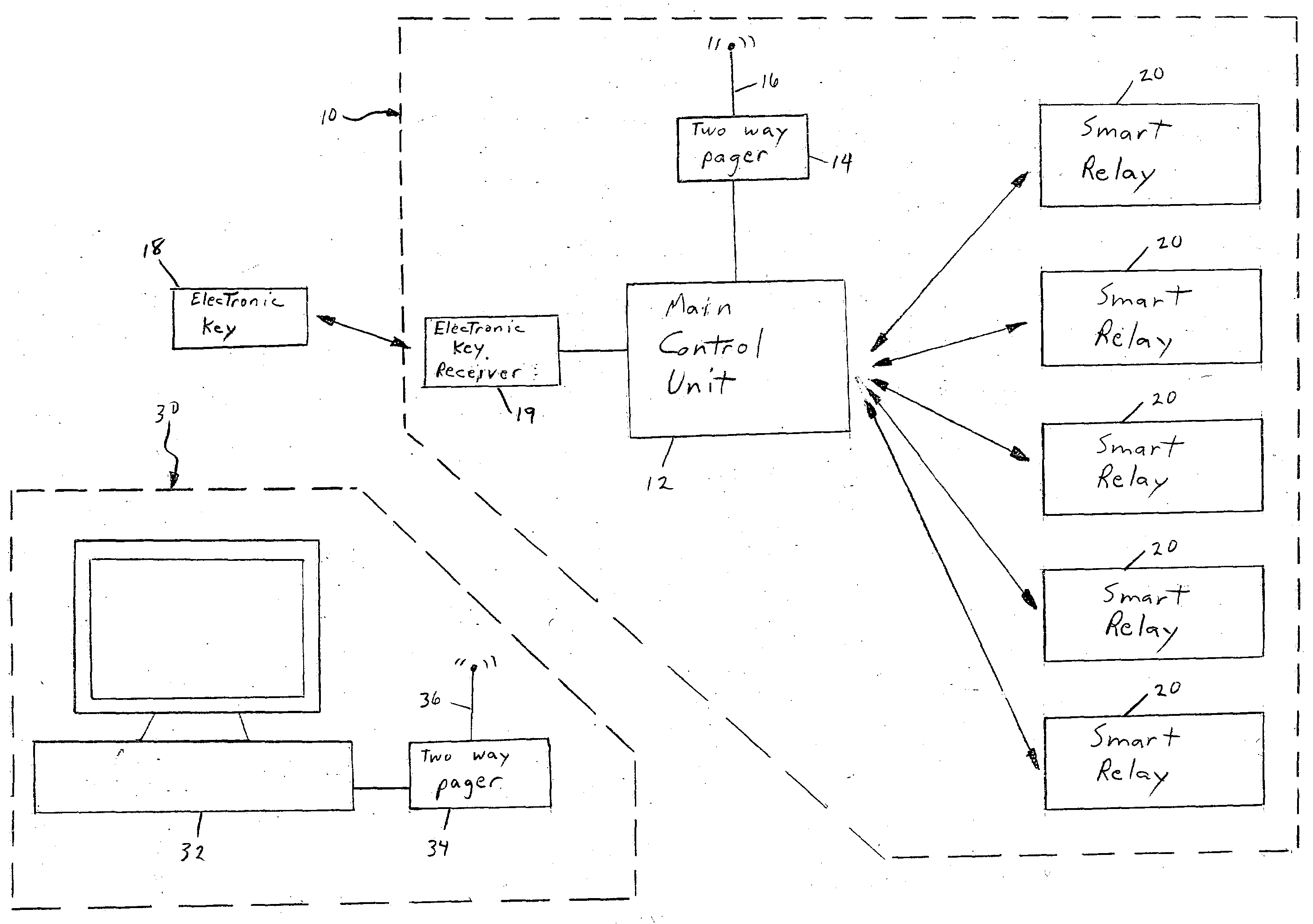
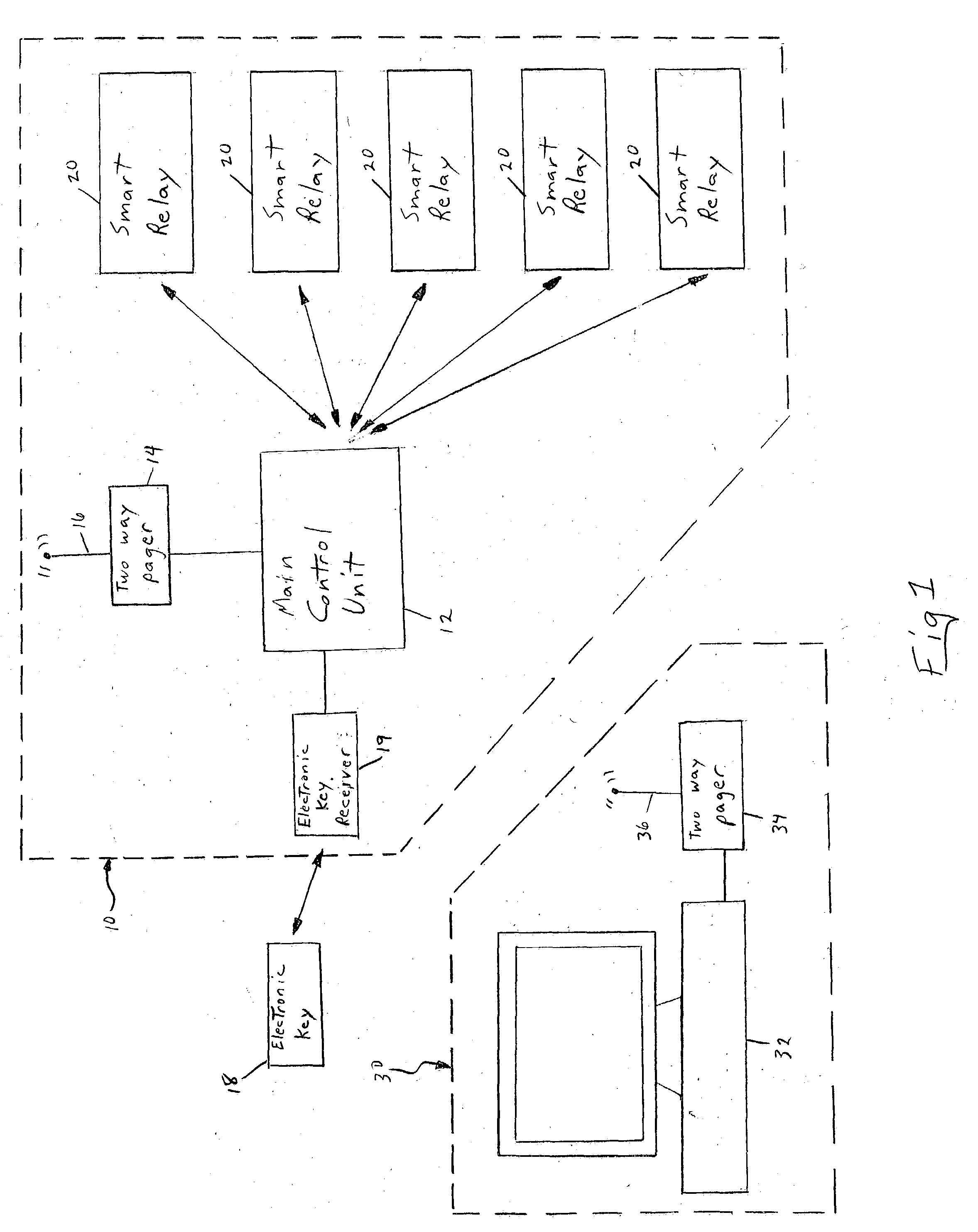
[0025] Referring to FIG. 1, a block diagram of the instant invention is shown illustrating the preferred system 10 which would be installed into a piece of mobile equipment, e.g. vehicle, construction machinery, farm equipment, airplane, boat, material handling equipment and the like, and linked via a wireless two-way pager and / or cellular connection to a remote base monitoring station 30. The equipment is protected by the security system 10 which incorporates the two-way paging device 14 in the security system main control unit 12. The base monitoring station 30 utilizes a computer 32 coupled to a similar two-way paging transmitter / receiver 34. Duri...


PUM


Abstract

The present invention relates to a security, telemetry and control system which utilizes wireless communication between a control unit and smart relay(s) within the vehicle and also utilizes wireless communication between the vehicle and a remote base station to monitor and protect a vehicle or piece of equipment against unauthorized users and thieves.

Description

FIELD OF THE INVENTION [0001] This invention relates to a combination security, telemetry and control system for mobile equipment such as vehicles, construction machinery, agricultural equipment or material handling units. A vehicle mounted main control unit provides wireless bi-directional communication with smart relays located within the vehicle and a remote base / control station located outside of the vehicle. BACKGROUND OF THE INVENTION [0002] Theft and unauthorized use of mobile pieces of equipment such as motor vehicles, construction equipment, aircraft and the like is widespread. Vehicle security systems are widely used to deter vehicle theft and vandalism, prevent theft of valuables from a vehicle, and to protect vehicle owners and occupants. A typical automobile security system includes a central processor unit (CPU) or controller connected by wire to a plurality of vehicle sensors. Typical sensors that monitor the vehicle may detect opening of the trunk, hood doors or wind...

Claims


Application Information

Patent Timeline
IPC IPC(8): G08C17/02
CPCG08C2201/42G08C17/02
Inventor KONG, QINSTEVENS, FRANK
Owner AUTOSAFE INT
Why Eureka
Try Eureka