
Exposure apparatus, optical projection apparatus and a method for adjusting the optical projection apparatus

Inactive Publication Date: 2005-01-20
NIKON CORP
View PDF88 Cites 8 Cited by
  • Summary
  • Abstract
  • Description
  • Claims
  • Application Information

AI Technical Summary

Benefits of technology

The present invention has been accomplished taking the above problems into consideration and an object of the present invention is to provide an exposure apparatus which can realize full scanning exposure of a large exposure area with excellent imaging performance and without lowering the throughput.
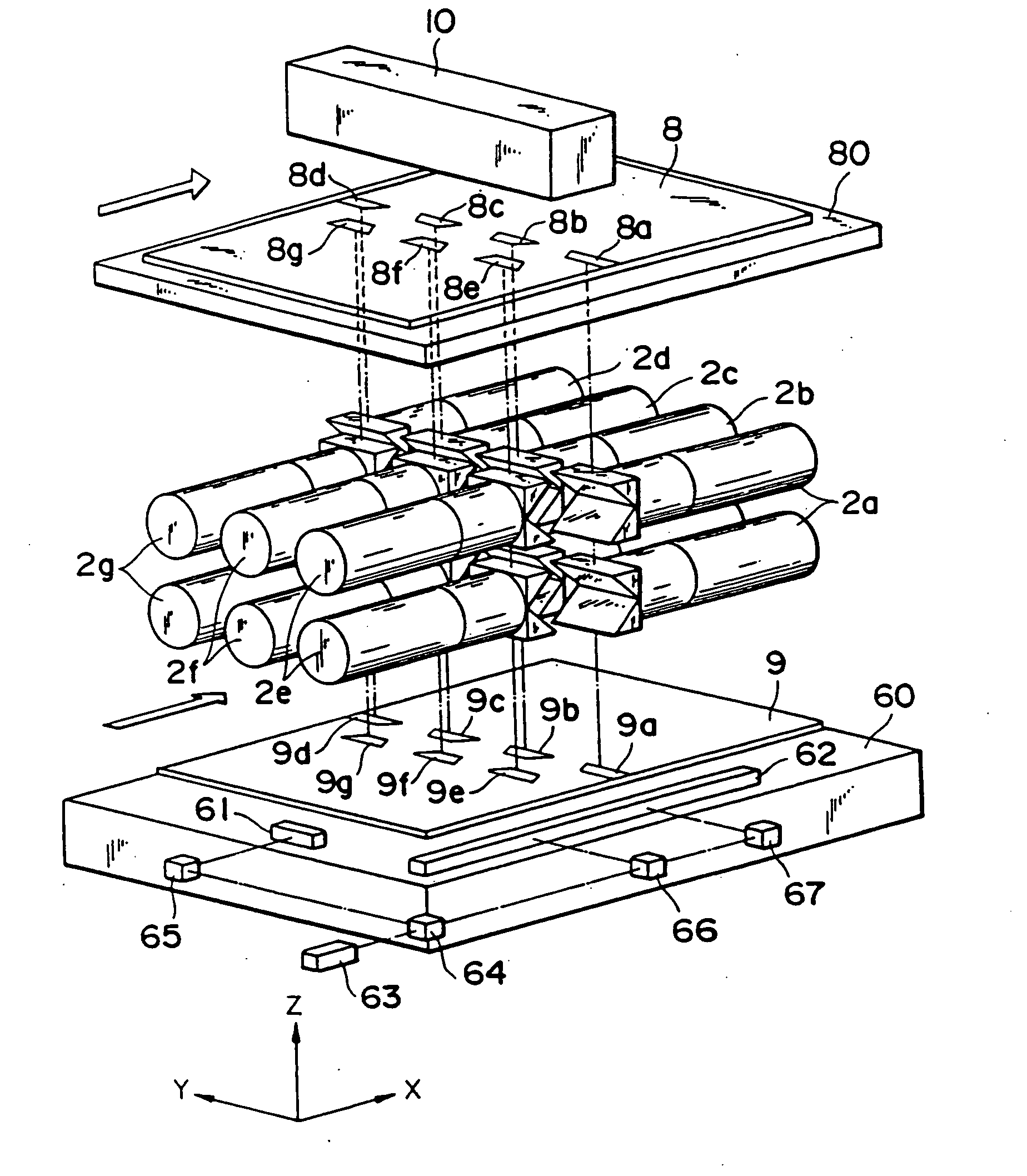
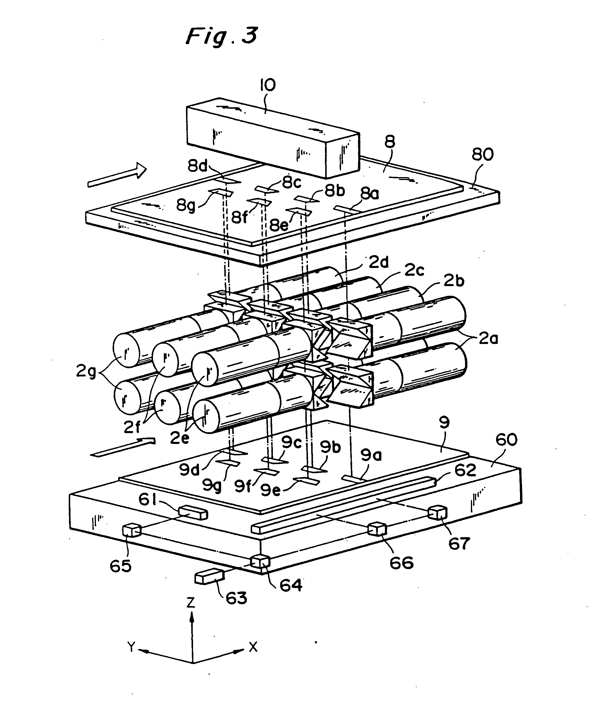
Since the plurality of projection optical systems are so arranged that the sum of widths of exposure regions along the scanning direction is constant over the direction perpendicular to the scanning direction, single scan exposure can achieve a large exposure area on the whole even with compact projection optical systems and small exposure regions formed thereby.
Also, since each projection optical system is compact, scanning exposure can be made while minimizing occurrence of aberrations and keeping excellent imaging performance.

Problems solved by technology

Because of this requirement, the method had such disadvantages that the magnification error of projection optical system must be decreased as close to 0 as possible, that the alignment accuracy must be greatly improved, and that the production cost of the apparatus is increased.
In order to increase the scale of projection optical system, however, large-scale optical elements must be produced with very high accuracy, which results in increasing the production cost and the size of apparatus.
Also, there was a disadvantage that the size increase of projection optical system caused an increase in aberrations or a decrease in imaging performance.

Method used


Image

  • Exposure apparatus, optical projection apparatus and a method for adjusting the optical projection apparatus
  • Exposure apparatus, optical projection apparatus and a method for adjusting the optical projection apparatus
  • Exposure apparatus, optical projection apparatus and a method for adjusting the optical projection apparatus

Examples


second embodiment

the present invention is next described referring to the accompanying drawings.

FIG. 18 is a perspective view to show the structure of an exposure apparatus according to the second embodiment of the present invention. Also, FIG. 19 is a drawing to show the structure of projection optical systems in the exposure apparatus of FIG. 18.

The second embodiment is different from the embodiment as shown in FIG. 3 in that the structure of projection optical systems 302a-302g is different from that in the first embodiment as detailed below and in that because of it the shape of field regions 308a-308g and exposure regions 309a-309g is substantially of a semi-circular ring. The second shown in FIG. 18 is the same as the first embodiment shown in FIG. 3 except for the above points.

FIG. 19 is a drawing to schematically show the structure of each projection optical system. A projection optical system as shown is composed of a first partial optical system 321-323, a field stop 324, and a second p...

seventh embodiment

The seventh embodiment employed such an arrangement that an exposure amount in the overlap region was made equal to that in the exposure region other than the overlap region by the shape of the aperture portion in the field stop FS, but a light-reducing filter or a filter with dot patterns may be provided at the end portions of the aperture portion in the field stop.

In the seventh embodiment, there is a possibility that where there are fabrication errors of the quarter wave plate 7H1 or the polarizing beam splitter 7PR1, s-polarized light is mixed in the p-polarized light traveling from the lens unit 702 to the field stop FS whereby the s-polarized light component reaches the plate 9. There is also a possibility that where there are fabrication errors of the polarization bean splitter 7PR2, this polarizing beam splitter 7PR2 reflects the p-polarized light traveling from the lens unit 2 to the field stop FS whereby the p-polarized light reaches the plate 9.

In such cases, the prima...


PUM


Abstract

A scanning projection exposure apparatus transfers a pattern of a mask onto a photosensitive substrate while moving the photosensitive substrate along a scanning direction. The scanning projection exposure apparatus can include an illumination optical system optically connected to a light source, and a projection optical system arranged in an optical path between the mask and the substrate. The illumination optical system illuminates the mask with linearly polarized light whose polarization direction extends along one of the scanning direction and a direction perpendicular to the scanning direction, without losses in quantity of light. The illumination optical system of the scanning projection exposure apparatus also can include a wave plate which is rotatable about a traveling direction of the light.

Description

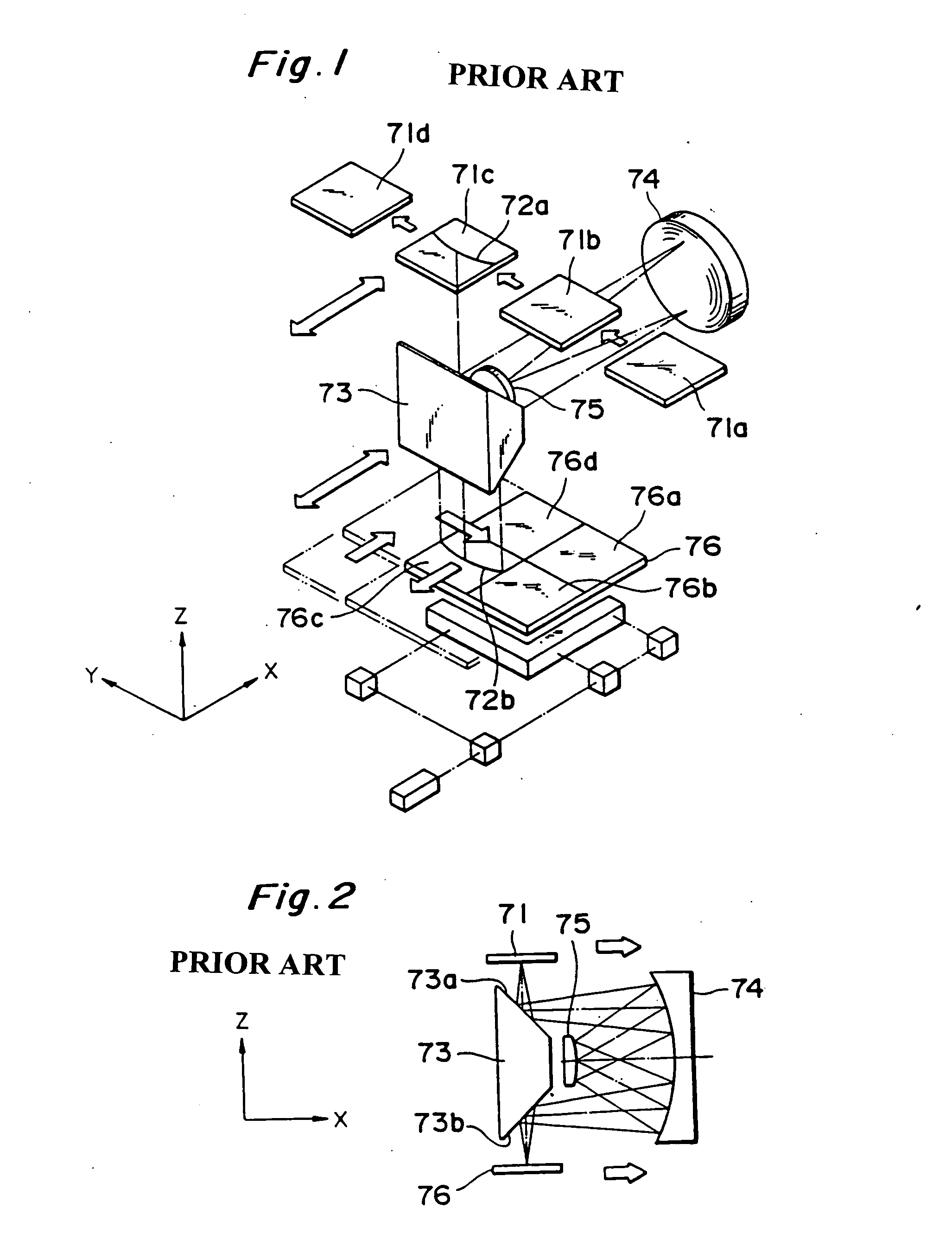
BACKGROUND OF THE INVENTION 1. Field of the Invention The present invention relates to an exposure apparatus, and more particularly to a scanning projection exposure apparatus which performs exposure while moving a first object and a second object. 2. Related Background Art Liquid crystal display panels are frequently used these days as a display device for word processors, personal computers, televisions, etc. A liquid crystal display panel is fabricated by patterning of transparent thin-film electrodes in a desired shape on a glass substrate by the photolithography technique. As an apparatus for the lithography a mirror projection type aligner is used for exposure-printing an original pattern formed on a mask onto a photoresist layer on a glass substrate through a projection optical system. FIG. 1 and FIG. 2 are drawings to show the structure of a conventional mirror projection type aligner. FIG. 1 is a perspective view to show the overall structure of the aligner and FIG. 2 i...

Claims


Application Information

Patent Timeline
IPC IPC(8): G02B13/22G02B17/00G02B17/06G02B17/08G02B27/10G03F7/20
CPCG03F7/70358G03F7/70275G02B13/22G02B17/002G02B17/008G02B17/045G02B17/0605G02B17/08G02B17/0812G02B17/082G02B17/0828G02B17/086G02B17/0892G02B27/144G02B27/145G03B27/32G03F7/70066G03F7/70216G03F7/70225G03F7/70241G03F7/70791
Inventor TANAKA, MASASHIKUMAZAWA, MASATOKATO, KINYAKATO, MASAKICHIBA, HIROSHISHIRASU, HIROSHI
Owner NIKON CORP
Learn More