Raman amplifier and optical transmission system
a technology of amplifier and optical transmission system, applied in the field oframan amplifier, can solve the problems of insufficient wide-band raman amplifier, increased device size, and limited pump light bandwidth for raman amplification,
- Summary
- Abstract
- Description
- Claims
- Application Information
AI Technical Summary
Benefits of technology
Problems solved by technology
Method used
Image

Examples
first embodiment
[0023] First Embodiment
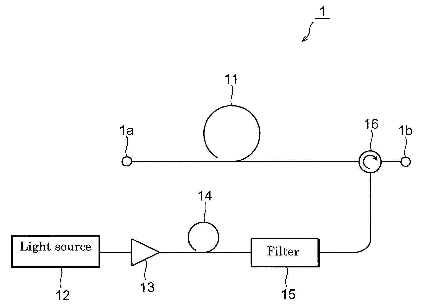
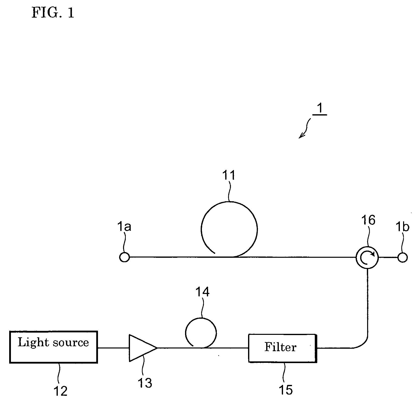
[0024] A Raman amplifier 1 constructed in accordance with a first embodiment of the present invention is described below with reference to FIGS. 1 through 4. Reference is first made to FIG. 1. The Raman amplifier 1 causes signal light input into an input terminal 1a to undergo Raman amplification and outputs the amplified signal light from an output terminal 1b. The Raman amplifier 1 includes an optical fiber for Raman amplification (hereinafter referred to as the “Raman-amplification optical fiber”) 11, a light source 12, an optical amplifier 13, a supercontinuum (SC) optical fiber (wide-band-light generating means) 14, an optical filter 15, and an optical circulator (pump-light supply means) 16.
[0025] The Raman-amplification optical fiber 11, which is an optical fiber exhibiting a highly non-linear characteristic, receives pump light for Raman amplification output from the optical circulator 16 and causes signal light input from the input terminal 1a to und...
second embodiment
[0040] Second Embodiment
[0041] A Raman amplifier 2 constructed in accordance with a second embodiment of the present invention is described below with reference to FIGS. 5 through 6B. The Raman amplifier 2 of FIG. 5, which causes signal light input from an input terminal 2a to undergo Raman amplification and outputs the signal light from an output terminal 2b, includes a Raman-amplification optical fiber 21, a light source 22, an SC optical fiber 24, and a wavelength division multiplexing (WDM) optical coupler 27.
[0042] The Raman-amplification optical fiber 21, which is a highly non-linear optical fiber, receives pump light for Raman amplification output from the WDM optical coupler 27, and causes signal light input from the input terminal 2a to undergo Raman amplification while the signal light is being propagated therethrough. The light source 22 outputs pulse light. The SC optical fiber 24, which serves as the wide-band-light generating means, allows the pulse light output from ...
third embodiment
[0049] Third Embodiment
[0050] A Raman amplifier 3 constructed in accordance with a third embodiment of the present invention is described below with reference to FIGS. 7 and 8. The Raman amplifier 3 of FIG. 7 causes signal light, which has been input from an input terminal 3a, to undergo Raman amplification, and outputs the amplified signal light from an output terminal 3b. The Raman amplifier 3 includes a Raman-amplification optical fiber 31, a light source 32, an optical amplifier 33, a SC optical fiber 34, an optical circulator 36, and a variable attenuator 38.
[0051] The Raman-amplification optical fiber 31, which is a highly non-linear optical fiber, receives pump light for Raman amplification output from the optical circulator 36, and causes the signal light input from the input terminal 3a to undergo Raman amplification while it is propagated therethrough. The light source 32 outputs pulse light. The optical amplifier 33 amplifies the pulse light output from the light source ...
PUM
| Property | Measurement | Unit |
|---|---|---|
| wavelength | aaaaa | aaaaa |
| wavelength range | aaaaa | aaaaa |
| wavelength range | aaaaa | aaaaa |
Abstract
Description
Claims
Application Information
 - R&D
- Intellectual Property
- Life Sciences
- Materials
- Tech Scout
- Unparalleled Data Quality
- Higher Quality Content
- 60% Fewer Hallucinations
Browse by: Latest US Patents, China's latest patents, Technical Efficacy Thesaurus, Application Domain, Technology Topic, Popular Technical Reports.
© 2025 PatSnap. All rights reserved.Legal|Privacy policy|Modern Slavery Act Transparency Statement|Sitemap|About US| Contact US: help@patsnap.com