System for releasing gas into molten metal

a technology of gas and molten metal, which is applied in the direction of machines/engines, liquid fuel engines, positive displacement liquid engines, etc., can solve the problems of low pressure behind, less interaction between the gas and the molten metal, and one or more of the components used to transfer the gas into the molten metal may be susceptible to breakage, so as to reduce the stress and wear of components, reduce the amount of pressure, and the effect of large cross-sectional area

Inactive Publication Date: 2005-01-20
COOPER PAUL V
View PDF98 Cites 103 Cited by
  • Summary
  • Abstract
  • Description
  • Claims
  • Application Information

AI Technical Summary

Benefits of technology

[0014] As molten metal moves through the metal-transfer conduit from the first section to the second section, its velocity slows when it enters the second section because of the larger cross-sectional area. Gas is released in either the first section or the second section through a gas-release opening into the molten metal stream and the m

Problems solved by technology

One problem with releasing gas into a metal-transfer conduit is that, in some systems, the conduit that transfers the gas from a gas source into the molten metal stream (called a gas-transfer conduit) typically extends into the metal-transfer conduit, usually extending downward from the top of the metal-transfer conduit, and disrupts the flow of molten metal passing through the conduit thereby creating a low-pressure area behind the portion of the gas-transfer conduit extending into the metal-transfer conduit.
The low-pressure area can interfere with the released gas mixing with molten metal passing through the metal-transfer conduit because, among other things, the gas immediately rises into the low-pressure area instead of mixing with molten metal throughout the metal-transfer conduit.
One problem with releasing gas into a molten meta

Method used


Image

  • System for releasing gas into molten metal
  • System for releasing gas into molten metal
  • System for releasing gas into molten metal

Examples


Embodiment Construction

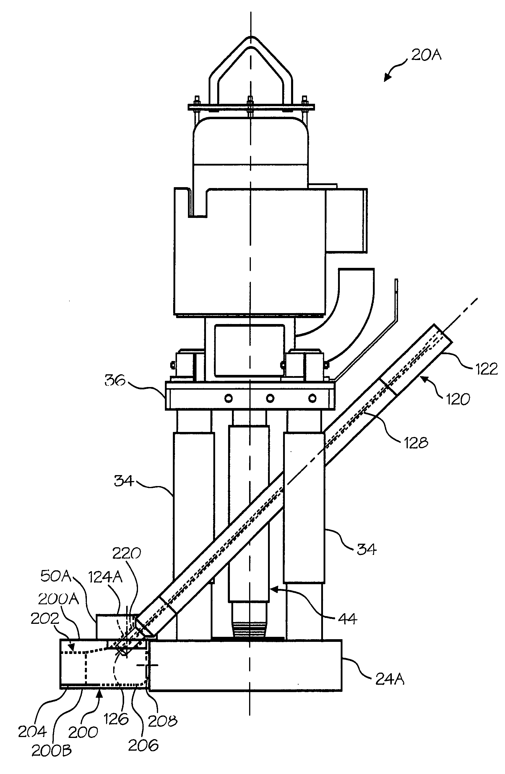
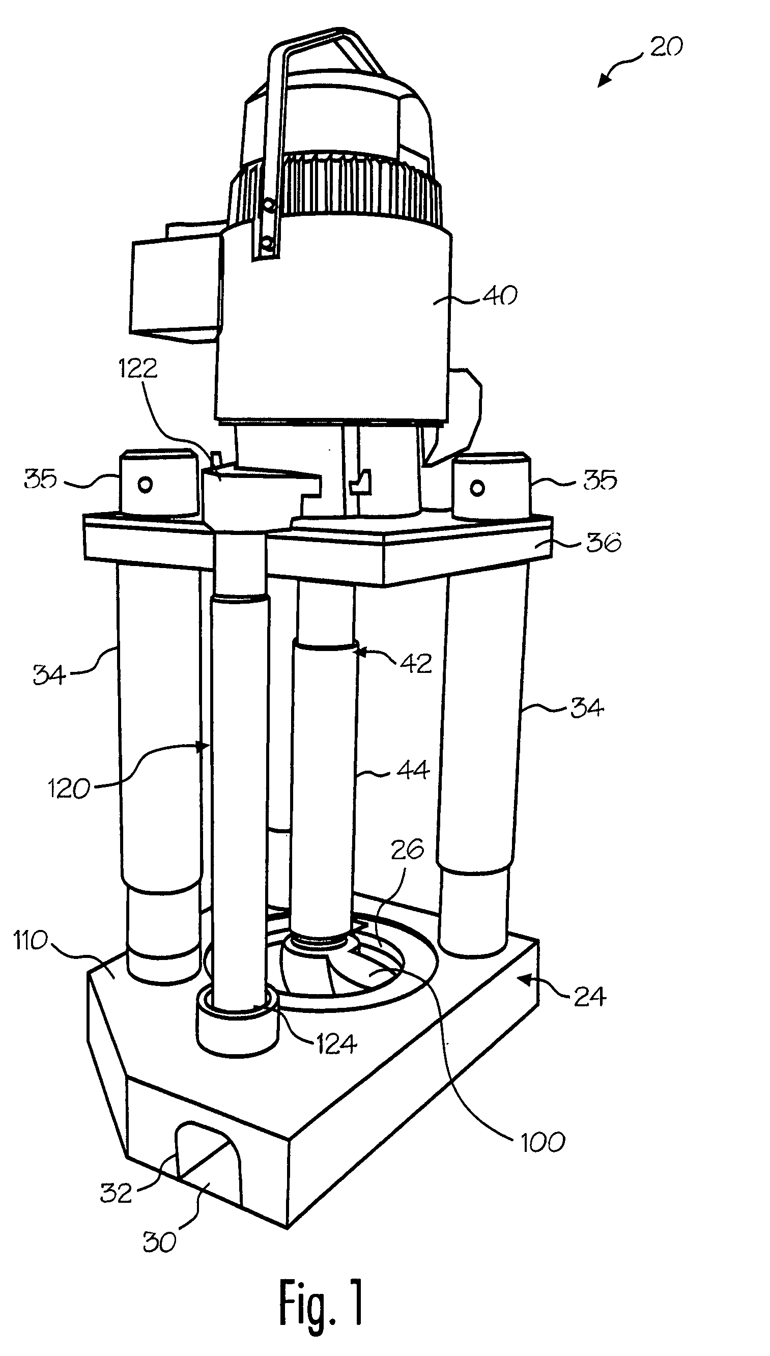
[0031] Referring now to the drawing where the purpose is to illustrate and describe different embodiments of the invention, and not to limit same, FIG. 1 shows a molten metal pump 20 that includes a device 100 in accordance with the present invention. When in operation, pump 20 is usually positioned in a molten metal bath in a pump well, which is usually part of the open well of a reverbatory furnace.

[0032] The components of pump 20, including device 100, that are exposed to the molten metal are preferably formed of structural refractory materials, which are resistant to degradation in the molten metal. Carbonaceous refractory materials, such as carbon of a dense or structural type, including graphite, graphitized carbon, clay-bonded graphite, carbon-bonded graphite, or the like have all been found to be most suitable because of cost and ease of machining. Such components may be made by mixing ground graphite with a fine clay binder, forming the non-coated component and baking, and...


PUM

PropertyMeasurementUnit
Fractionaaaaaaaaaa
Fractionaaaaaaaaaa
Pressureaaaaaaaaaa

Abstract

A device for releasing gas into molten metal includes a base having a discharge. The discharge has a first section including a first cross-sectional area and a second section including a second cross-sectional area, wherein the first section is upstream of the second section and the first cross-sectional area is smaller than the second cross-sectional area. A gas-release opening is positioned so that it can release gas into one or more of the first section or the second section. As the molten metal moves from the first cross-sectional area to the second cross-sectional area gas is released into the molten metal and the molten metal flow helps to draw the gas into the flow, thereby lowering the pressure required to release gas into the molten metal. Metal-transfer conduits other than a discharge incorporated in a pump base are also disclosed, as are pumps including either a discharge or other metal-transfer conduit according to the invention.

Description

FIELD OF THE INVENTION [0001] The invention relates to releasing gas into molten metal and more particularly, to a device for releasing gas into a stream of molten metal utilizing the flow of the molten metal stream to assist in drawing the gas into the stream. In this manner, the gas may be released at a relatively low pressure as compared to known devices. BACKGROUND OF TH INVENTION [0002] As used herein, the term “molten metal” means any metal or combination of metals in liquid form, such as aluminum, copper, iron, zinc and alloys thereof. The term “gas” means any gas or combination of gases, including argon, nitrogen, chlorine, fluorine, freon, and helium, which are released into molten metal. [0003] Known pumps for pumping molten metal (also called “molten-metal pumps”) include a pump base (also called a housing or casing), one or more inlets, an inlet being an opening to allow molten metal to enter a pump chamber (and is usually an opening in the pump base that communicates wi...

Claims


Application Information

Patent Timeline
IPC IPC(8): F04D7/06F04D13/02F04D29/02
CPCY10T428/12F04D15/0044F04D29/2227F04D29/026F04D7/00F04D13/021F04D7/065F04D29/2216F04D29/4213F05D2250/52F04D29/426C21C7/072C21C1/06C21C5/30
Inventor COOPER, PAUL V.
Owner COOPER PAUL V
Why Eureka
Try Eureka