
Heat-transfer systems

Active Publication Date: 2005-01-20
PRIMIENT COVATION LLC
View PDF5 Cites 10 Cited by
  • Summary
  • Abstract
  • Description
  • Claims
  • Application Information

AI Technical Summary

Benefits of technology

[0008] A further primary object and feature of the present invention is to provide an improved system for providing heat to thermally dependent processes. It is a further object and feature of the present invention to provide such a system capable of reduced energy consumption.
[0009] It is a further object and feature of the present invention to provide such a system capable of dramatically reducing the fire-damage risks associated with fires involving heat-transfer fluids.
[0010] It is a further object and feature of the present invention to provide such a system capable of a significantly longer fluid life.
[0011] It is a further object and feature of the present invention to provide such a system reducing the amount of maintenance required in endothermic industrial processes. It is a further object and feature of the present invention to provide such a system capable of reduced corrosion. It is a further object and feature of the present invention to provide such a system capable of reduced toxicity.
[0012] It is a further object and feature of the present invention to provide a heat-transfer fluid for endothermic industrial processes that can be extinguished with water in case of fire.
[0013] It is a further object and feature of this invention to provide a heat-transfer fluid that is low toxicity, minimally corrosive, low-maintenance, durable, and water extinguishable.

Problems solved by technology

Unfortunately, such hydrocarbon fluids are typically not biodegradable and are deemed environmentally hazardous.
Also, among other problems, they have relatively low thermal conductivity and thus may demand excessive amounts of energy.
In addition, they are highly flammable and not water-miscible so that traditional water sprinkler systems fail to suppress fires involving such hydrocarbon fluids.
Industrial entities utilizing endothermic processes consume large amounts of energy in order to supply heat during the endothermic processes.
Furthermore, particulate waste byproduct is created, resulting in further cleaning and toxic-waste type disposal costs.
Additionally, as hydrocarbon heat-transfer fluids are extremely flammable, fires involving hydrocarbon heat-transfer fluids have resulted in tremendous property damage, economic loss, injuries and death.
For example, in 1989, a leak at a plastics manufacturing plant in Pasadena, Tex., caused a fire that killed 22 and injured 80.
To date, the efforts that have been made worldwide to minimize the risk of fire involving machines using hydrocarbon heat-transfer fluids in thermally-dependent processes have not solved this problem.

Method used


Image

  • Heat-transfer systems
  • Heat-transfer systems
  • Heat-transfer systems

Examples


Embodiment Construction

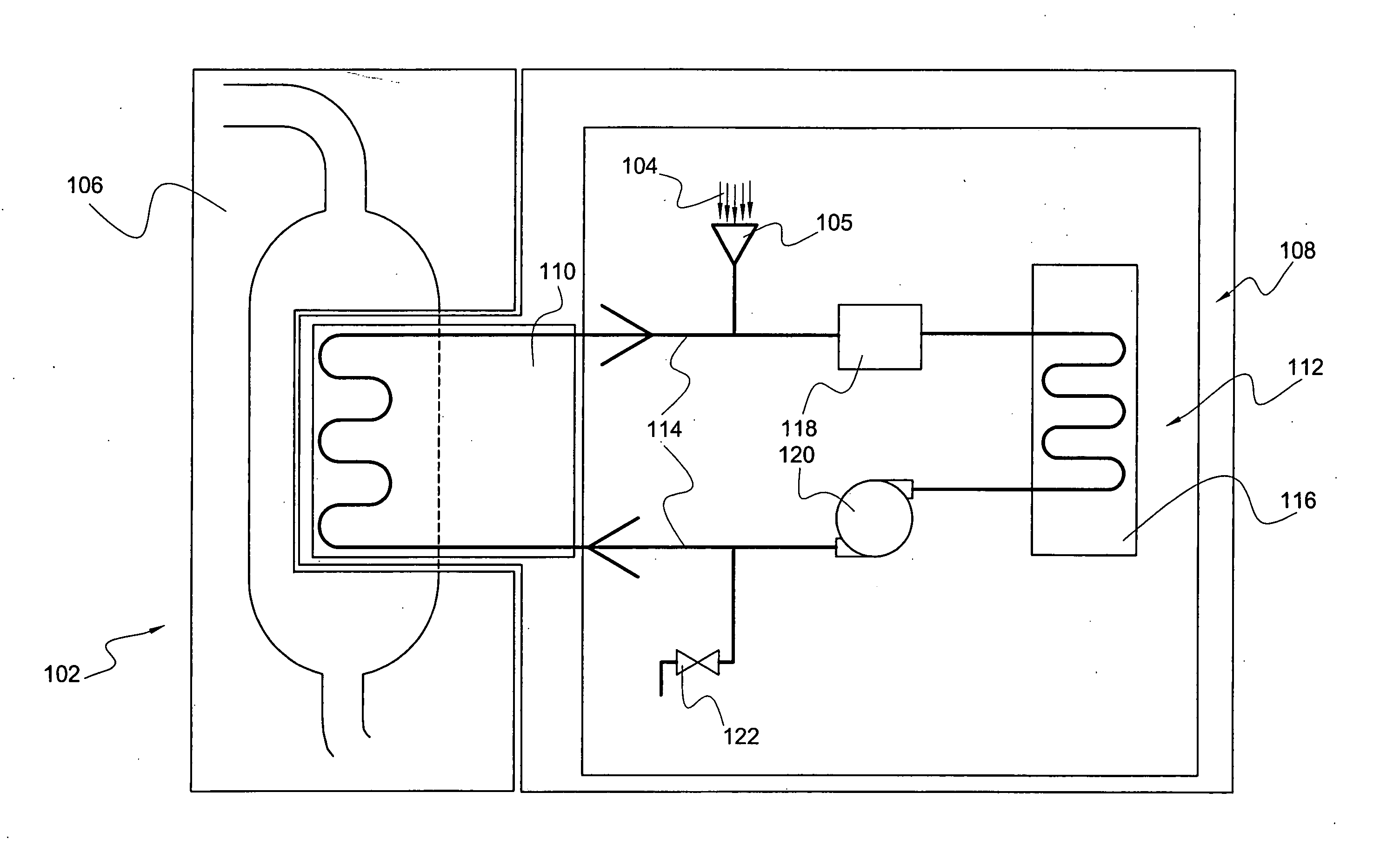
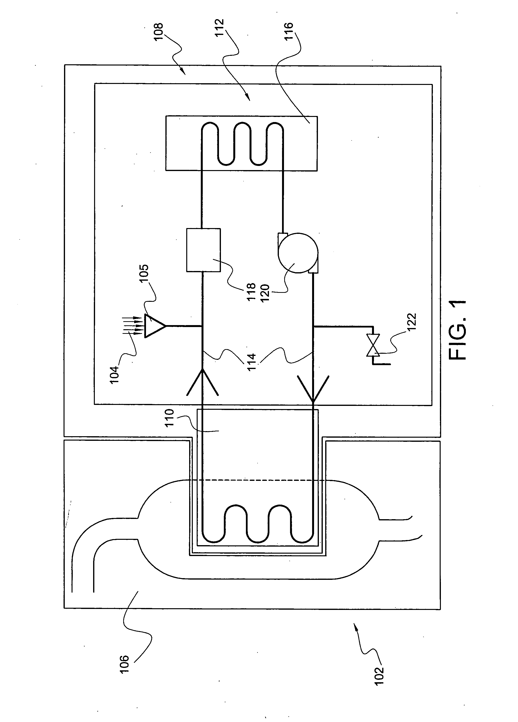
[0066]FIG. 1 is a diagrammatic representation of the heat-transfer system, according to a preferred embodiment of the present invention. Preferably, heat-transfer system 102 comprises heat-transfer fluid 104 (at least embodying herein heat-transfer fluid means for transferring heat, without substantial chemical breakdown, at temperatures of about 150 degrees Celsius to about 200 degrees Celsius); endothermic industrial processor 106 (at least embodying herein industrial processor means for endothermic industrial processing); heater 116 (at least embodying herein heater means for controllably transferring heat to said heat-transfer fluid means); heat-transfer element 110 (at least embodying herein heat transfer means for controllably transferring heat from said heat-transfer fluid means to said industrial processor means); and circulator 114 (at least embodying herein circulating means for circulating said heat-transfer fluid means among said heater means and said heat transfer means...


PUM


Abstract

An improved system for transferring heat, utilizing diols, specifically 1,3-propanediol (PDO). The system reduces the energy consumption, maintenance costs, corrosion, toxicity, and the risk of fire associated with such heat-dependent processes. Unlike traditional hydrocarbon heating fluids, diols do not require draining and replacement if a purifier is installed in the system. Business methods are also disclosed.

Description

CROSS-REFERENCE TO RELATED APPLICATION [0001] The present application claims priority from and is related to prior provisional application Ser. No. 60 / 485,441, filed Jul. 7, 2003, entitled “HEAT TRANSFER SYSTEM”, the contents of which are incorporated herein by this reference and are not admitted to be prior art with respect to the present invention by the mention in this cross-reference section.BACKGROUND [0002] This invention relates to heat-transfer systems. More particularly, it relates to providing a system for improved heat transfer in processes requiring the input of thermal energy. [0003] Typically, hydrocarbon fluids have been used for transferring heat in high-temperature-dependent processes. Unfortunately, such hydrocarbon fluids are typically not biodegradable and are deemed environmentally hazardous. Also, among other problems, they have relatively low thermal conductivity and thus may demand excessive amounts of energy. In addition, they are highly flammable and not wa...

Claims


Application Information

Patent Timeline
IPC IPC(8): B01J19/00B01J47/00C09K5/10F28D15/00
CPCB01J19/0013B01J19/002B01J47/00F28D15/00B01J2219/00103B01J2219/00265C09K5/10B01J2219/0009
Inventor EATON, EDWARDKUDCEY, SCOT D.
Owner PRIMIENT COVATION LLC
Learn More