Power supply unit

Inactive Publication Date: 2005-01-20
PANASONIC CORP
View PDF64 Cites 27 Cited by
  • Summary
  • Abstract
  • Description
  • Claims
  • Application Information

AI Technical Summary

Benefits of technology

[0019] To solve the above-mentioned problem, a power supply unit of the present invention has the following configuration. The power supply unit from one aspect of the present invention comprises a fuel cell using methanol as fuel; a secondary battery for supplying power to a load; a fuel cell control part for controlling the amount of fuel and/or air supplied to the above-mentioned

Problems solved by technology

However, the secondary battery cannot feed or supply electric power to the personal computer for longer than about four consecutive hours.
The prior art circulating type fuel cell has the deficiency of discharging a considerable amount of methanol along with carbon dioxide because of the difficulty in separating only carbon dioxide from the used fuel.
For this reason, less than 10% of the amount of supplied methanol becomes available power, resulting in a low fuel utilization rate (details to be described later).
In the fuel cell, some delay occurs until the output power of the fuel cell is increased or decreased by increasing or decreasing the amount of fuel supplied to the fuel cell.
This results in lowering of fuel utilization rate of the fuel cell.
The fuel cell using methanol as fuel has the problem of discharging a large amount of methano

Method used


Image

  • Power supply unit
  • Power supply unit
  • Power supply unit

Examples


first embodiment

[0071] Referring to FIGS. 1 to 6, a power supply unit of a first embodiment will be described.

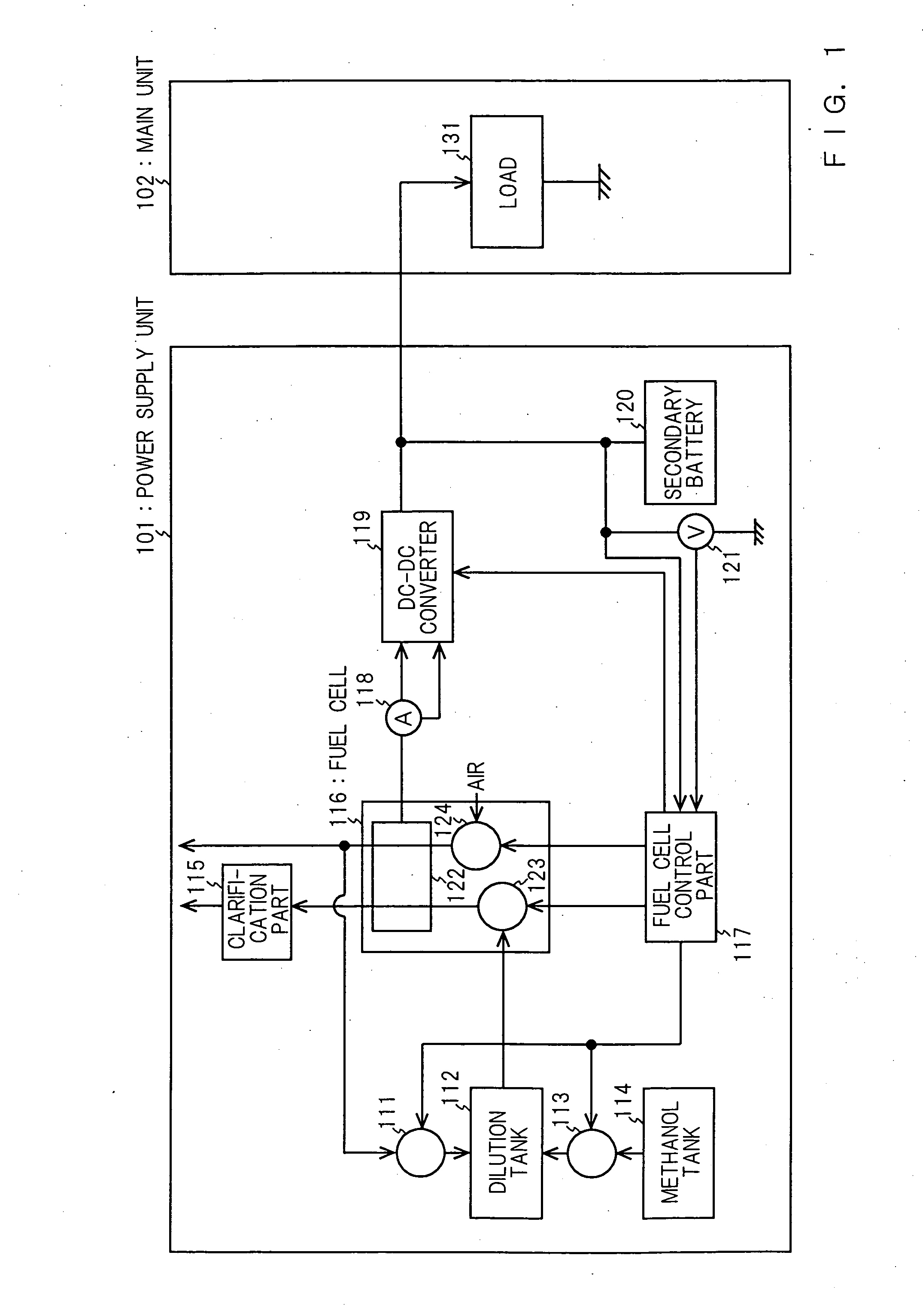
[0072] Firstly, the configuration of the power supply unit in accordance with the first embodiment will be described. FIG. 1 is a block diagram showing the configuration of the power supply unit in accordance with the first embodiment. FIG. 1 shows a power supply unit 101 and a main unit 102. The power supply unit 101 has a return pump 111, a dilution tank 112, a methanol pump 113, a methanol tank 114, a clarification part 115, a fuel cell 116, a fuel cell control part 117, a fuel cell output current detector 118 for detecting output current of the fuel cell 116, a DC-DC converter 119, a secondary battery 120 and a secondary battery output voltage detector 121 for detecting the output voltage of the secondary battery 120. The fuel cell 116 has a stack 122, a fuel pump 123 and an air pump 124. The main unit 102 has a load 131, for instance, a CPU.

[0073] The fuel cell 116 is a balance type f...

second embodiment

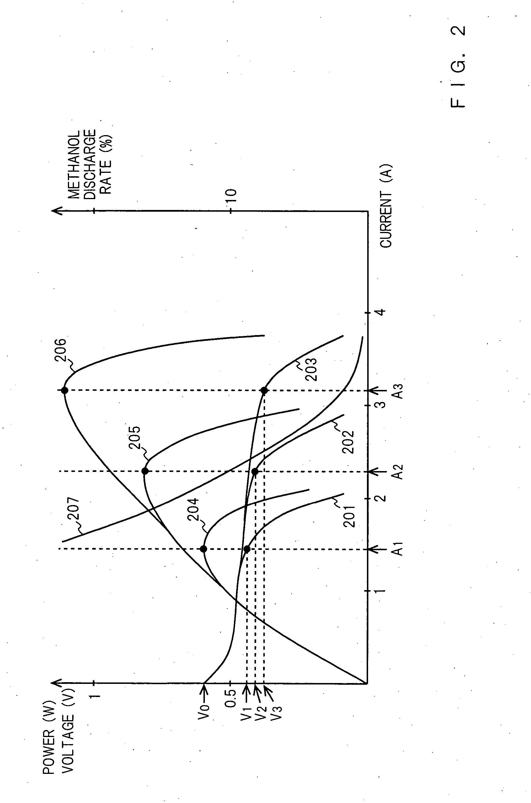
[0125]FIG. 2 is a graph showing output current-output voltage characteristic, output current-output power characteristic and output current-methanol discharge rate characteristic by amount of fuel of the balance type fuel cell of the power supply unit in accordance with the present invention. FIG. 2 has been already described. The output current-output voltage characteristic and output current-output power characteristic of the fuel cell 116 vary depending on the amount of fuel supplied to the fuel cell 116. Once the amount of fuel is determined to be a certain value, the output current-output voltage characteristic and output current-output power characteristic with the amount of fuel are determined uniquely.

[0126] In FIG. 2, in the case where the amount of fuel is 0.1 cc / min, the output power of the fuel cell 116 becomes maximized at a voltage V1 and a current A1. In the case where the amount of fuel is 0.2 cc / min, the output power of the fuel cell 116 becomes maximized at a volta...


PUM


Abstract

A clean power supply unit with a high fuel utilization rate using a fuel cell is provided. The power supply unit of the present invention comprises a fuel cell using methanol as fuel; a secondary battery for supplying power to a load; a fuel cell control part for controlling the amount of fuel and/or air supplied to the above-mentioned fuel cell; and a power converter for converting the power output from the above-mentioned fuel cell to a predetermined voltage or current, supplying power to the load and/or the above-mentioned secondary battery and controlling the supplied power so as to fall within a predetermined range including the value at which the amount of methanol discharged from the above-mentioned fuel cell becomes minimized.

Description

BACKGROUND OF THE INVENTION [0001] The present invention relates to a power supply unit. [0002] In portable electronic and electrical equipments such as personal computer, a secondary battery such as lithium ion battery and nickel hydrogen battery has been used as a power supply unit. However, the secondary battery cannot feed or supply electric power to the personal computer for longer than about four consecutive hours. Recently, a fuel cell capable of feeding electric power to the personal computer for 20 to 40 consecutive hours has been getting a lot of attention. [0003] A circulating type unit is a typical unit of a fuel cell using methanol as fuel. FIG. 9 is a block diagram showing the configuration of a prior art circulating type fuel cell. FIG. 9 shows a return pump 111, a dilution tank 112, a methanol pump 113, a methanol tank 114, a fuel cell 116, a fuel cell control part 117 and a gas-liquid separator 901. The fuel cell 116 has a stack 122, a fuel pump 123 and an air pump ...

Claims


Application Information

Patent Timeline
IPC IPC(8): H01M8/04H01M8/10H01M10/42H01M16/00
CPCH01M8/04186H01M8/04656H01M8/0494Y02E60/50H01M10/42H01M16/006Y02E60/523H01M8/1009Y02E60/10
Inventor KOZU, KATSUMIICHINOSE, TOSHIHIKOTAKADA, MASAHIROSHIBUTANI, SATOSHIKURANAKA, SO
Owner PANASONIC CORP
Why Eureka
Try Eureka