Fuel cell manifold seal with rigid inner layer

a manifold seal and fuel cell technology, applied in the field of multi-layer reactant gas manifold seals, can solve the problems of unfavorable use of manifold-to-csa seals disclosed in the prior art, cell edge misalignment, uneven “skyline, etc., and achieve the effect of improving seal durability

Active Publication Date: 2005-01-20
AUDI AG
View PDF1 Cites 17 Cited by
  • Summary
  • Abstract
  • Description
  • Claims
  • Application Information

AI Technical Summary

Benefits of technology

[0012] enhanced seal durability...

Problems solved by technology

Generally, the dimensional tolerances of the individual cells and the position tolerances of the cells within the cell stack assembly result in cell edge misalignment, known as an uneven “skyline”, within the PEM cell stack assembly.
Although well suited for stationary fuel cell power plant applications, such manifold-to-CSA seals disclosed in the prior art have certain limitations when used in automobiles or other vehicles subject to the stresses of acc...

Method used


Image

  • Fuel cell manifold seal with rigid inner layer
  • Fuel cell manifold seal with rigid inner layer
  • Fuel cell manifold seal with rigid inner layer

Examples


Embodiment Construction

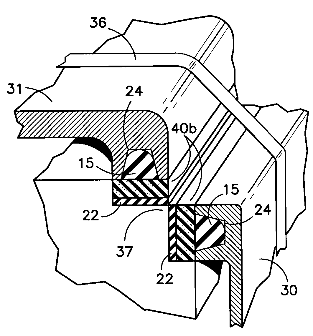
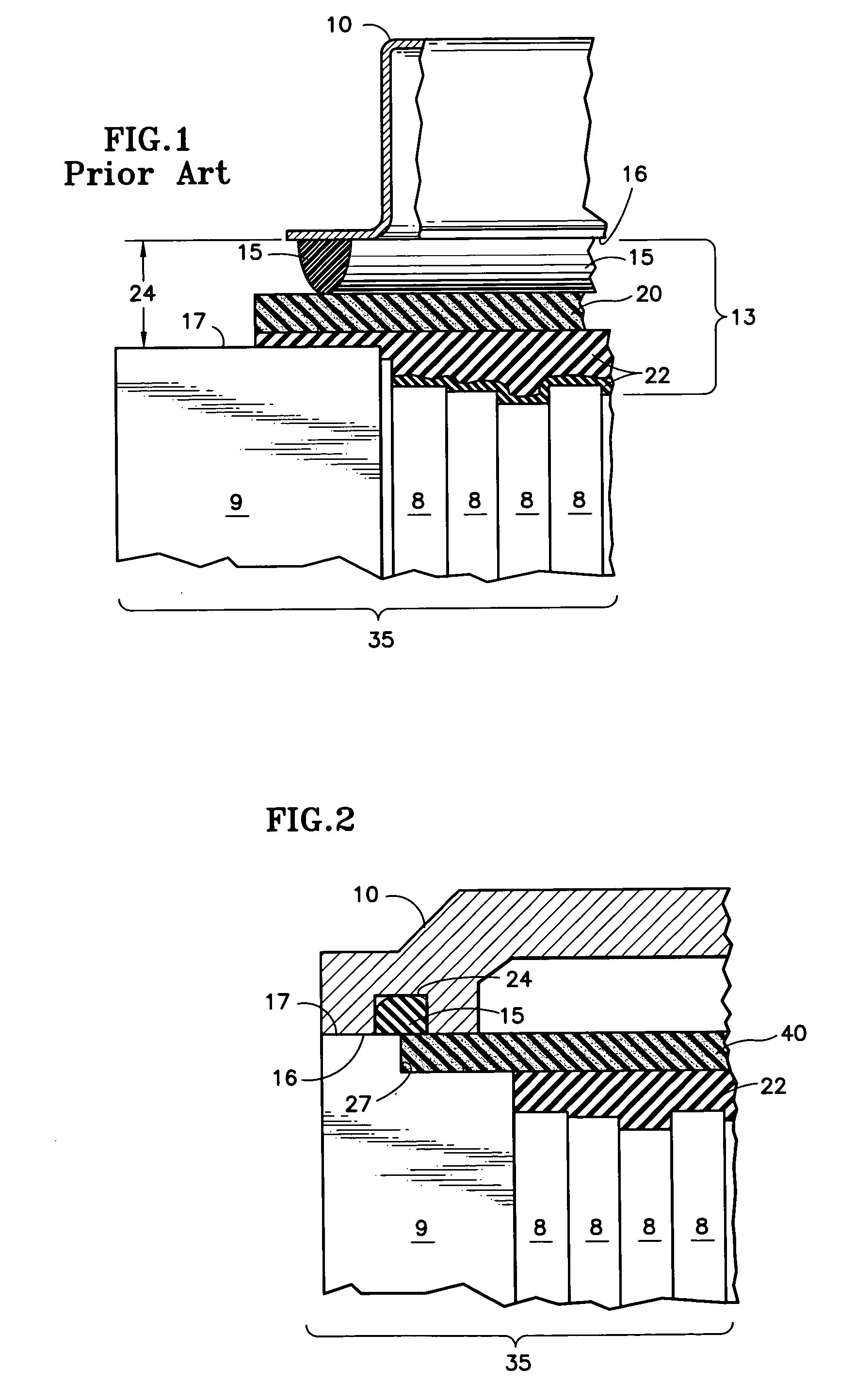
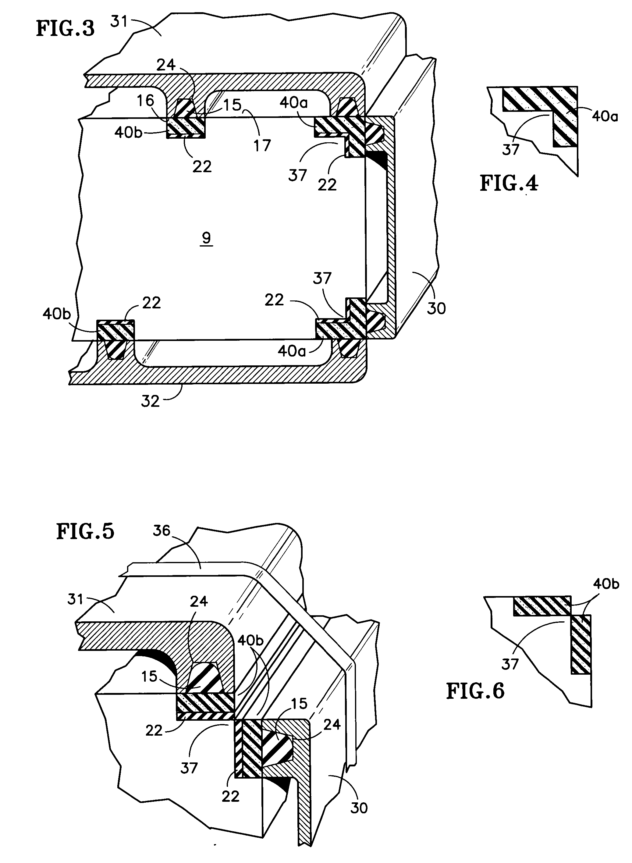
[0026] Referring to FIG. 2, a reactant gas manifold 10 is positioned above a cell stack assembly 35 having an uneven skyline. At least one silicone rubber filler layer 22, such as GE RTV 118, Shin Etsu KE3476T, or any compatible elastomer, is applied to the surface of the skyline to form a relatively flat, smooth surface above the cells 8.

[0027] Endplate 9 of the present invention includes a notch 27 to receive an end portion of a rigid dielectric strip 40 coplanar with the contact surface 17 of the endplates 9 and extending over the CSA sealing area to spread the sealing load uniformly. The rigid strip 40 may be adhesively secured to the skyline silicone rubber filler layer 22 and on the notch surfaces of the endplates 9. In order to prevent shorting of the cells 8, the rigid strip 40 must be a dielectric, such as a NEMA G11 fiberglass reinforced plastic, or a polymer-coated metal. Other dielectric composite materials or metallic materials with a dielectric coating, known to those...


PUM

PropertyMeasurementUnit
Forceaaaaaaaaaa

Abstract

A multi-layer seal system for a manifold (10) of a proton exchange membrane fuel cell includes a silicone rubber filler layer (22) between endplates (9) to compensate for the uneven edges of cell elements, an elastomer gasket (15) disposed within a groove (24) in the contact surfaces of a manifold (10), and a rigid dielectric strip (40) coplanar with the contact surfaces (17) of the endplates (9) interposed between the silicone rubber filler layer (22) and the gasket (15). The rigid dielectric strip (40) may be either angled (40a) for a corner seal, or flat (40b).

Description

TECHNICAL FIELD [0001] This invention relates to a multi-layer reactant gas manifold seal having a rigid inner layer for sealing a proton exchange membrane (PEM) fuel cell manifold to a fuel cell stack assembly. BACKGROUND ART [0002] A basic fuel cell comprises an anode electrode spaced apart from a cathode electrode with an electrolyte disposed between the two electrodes; each electrode includes a catalyst layer on the electrolyte side thereof. On the non-electrolyte side of the anode electrode is a reactant gas chamber for carrying a fuel, and on the non-electrolyte side of the cathode electrode is a reactant gas chamber for carrying an oxidant. The electrodes are constructed so that the gas diffuses therethrough and comes into contact with the electrolyte in the catalyst layer thereby causing a well-known electrochemical reaction whereby hydrogen ions and electrons are produced at the anode. The electrons travel from the anode electrode through an external circuit to the cathode ...

Claims


Application Information

Patent Timeline
IPC IPC(8): H01M8/02H01M8/24
CPCH01M8/0271Y10T29/4911Y02E60/50H01M8/2485
Inventor DAVE, NILESHKUMAR T.LIN, NING
Owner AUDI AG
Why Eureka
Try Eureka