
Portable body-felt vibration system

a body-felt vibration and portable technology, applied in mechanical vibration separation, chiropractic devices, physical therapy, etc., can solve the problems of inability to use at other places easily, risk of mistaken patient use of transducer, and inability to carry around, etc., to achieve convenient use, increase production cost, and increase production efficiency

Inactive Publication Date: 2005-01-20
KOJIMA YASUJI
View PDF5 Cites 15 Cited by
  • Summary
  • Abstract
  • Description
  • Claims
  • Application Information

AI Technical Summary

Benefits of technology

[0009] This invention is intended to provide an improved portable body-felt vibration system which may be used on a different type of body support gear including a regular bed and a chair. By providing the portable body-felt vibration system, the problems associated with fixed systems such as high production costs, longer production time, misusages by patients and cumbersome control of multiple systems will be solved. The improved portable system will also provide more convenient usage, more efficient vibration and less maintenance costs than existing systems.
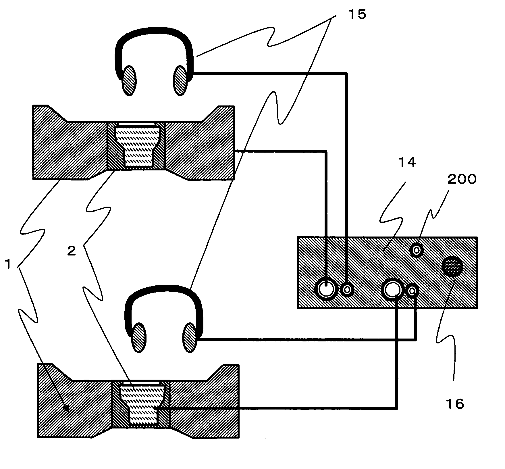
[0010] Therefore, objects of this invention include to provide a portable rough-rectangular vibration-transmitting cushion; to provide a guide that lead a user's backbones to the transducer's vibration transmitting plate; to reduce vibrations that are transmitted to a body support gear such as a chair back; to support a user's back to remain in a proper position; to separate a vibration-transmitting plane from other part of the vibration-transmitting surface and use different materials for the plane from the materials for other surface; to eliminate stitches over a vibration-transmitting plate of a transducer; to provide a control unit that can control multiple vibration output devices and sound output devices; and to provide a configuration of the cushion that can easily identify the mounting direction of the cushion.

Problems solved by technology

These types of body-felt vibration systems with a fixed transducer have a longer manufacturing time and a higher manufacturing cost because a transducer must be built in a body support component such as a bed or a chair.
When this type of body-felt vibration system is used at a hospital as a regular bed or a chair, there is a risk that the transducer is mistakenly used for a patient who must avoid vibration such as a pregnant woman since a transducer is fixed in a body support component.
As described above, the most of the body-felt vibration systems in prior arts are not portable and can not be used at other places easily.
(U.S. Pat. No. 5,442,710) These systems still have problems.
With these systems, we do not obtain efficient vibration from a transducer because there is no guide to lead a user's backbones to the top portion of the transducer.
In addition, in the prior arts there is no support to maintain the backbone on the right position; therefore, the efficient vibration is not obtained when the backbone is out of the right position.
There have been other types of problems in the body sensory acoustic systems of prior arts.
In this case, the vibration is transmitted to the body support component, and vibration generated by the transducer is not used efficiently.
Secondly, the part which covers a transducer and which is placed between a user's backbones and the transducer is easily worn out because of frictions.
However, there is no cost-effective solution for the worn-out.
Thirdly, since the body-felt vibration systems in prior arts are invented for stand-alone use, there has not been a controller which adjusts a vibration-volume of multiple body sensory acoustic systems.
The vibration-volume of body-felt vibration systems must be adjusted separately, and it was inconvenient at a place such as a hospital where multiple body sensory acoustic systems are used simultaneously.

Method used


Image

  • Portable body-felt vibration system
  • Portable body-felt vibration system
  • Portable body-felt vibration system

Examples


first embodiment

The First Embodiment

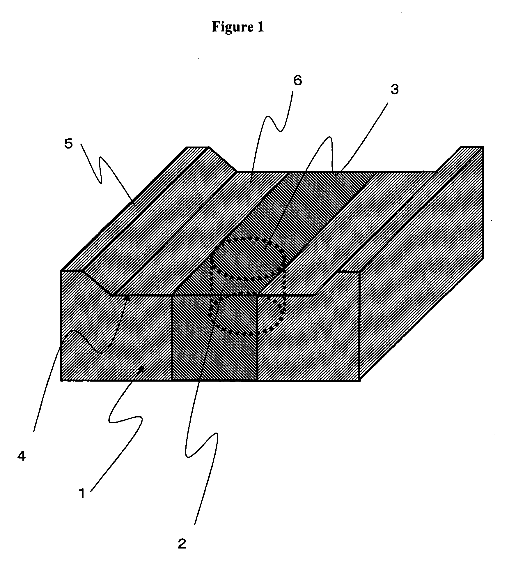
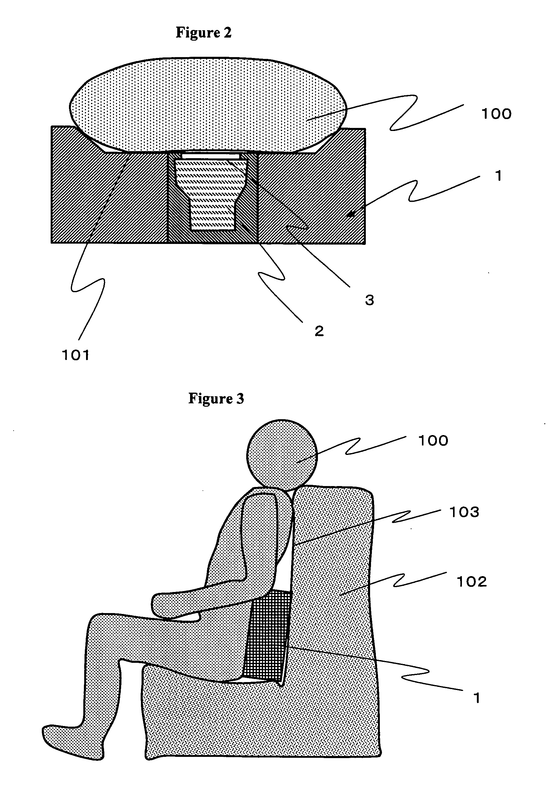
[0020] The first embodiment is explained with FIG. 1. FIG. 1 describes a waist cushion 1 of the body-felt vibration system of this invention. A transducer 2 is installed in a center part of said cushion and surrounded with polyurethane rubber. Outer shape of the cushion is a rough rectangle. The waist cushion has a vibration transmitting surface 4 that is connected to a vibration transmitting plate 3 of said transducer. The two facing edges of the vibration transmitting surface 4 are taller than other area creating banks 5. The vibrating plate 3 of said transducer is installed on hollow area 6 in the center of the cushion. When this device is used, said banks are placed on a user's back. The vibrating plate 3 in the hollow 6 is designed to be applied close to the user's backbones. The banks 5 guide the vibrating plate to the backbones of a user. FIGS. 2 and 3 describes how a user 100 is using the waist cushion 1. FIG. 2 is an image seen from above describing that...

second embodiment

The Second Embodiment

[0021] The second embodiment is explained with FIG. 4. This is an example of different material usage for the belt-shaped vibration transmitting plane 9 from other part. In this example, the vibration transmitting plane 9 is wider than the vibration plate width 7 and narrower than the hollow width 8. The vibration transmitting plane 9 is connected with other surrounding parts 11 on the stitches 10. The vibration plate 3 transmits strong vibrations; therefore, if stitches are over the vibration plate, the stitches are more likely to be worn out. However, in this example, the deterioration is reduced since there is no stitch over the vibration plate. In addition, if there are stitches over the vibration plate, the stitches create an uneven surface, which is pressed against the user's back, and deteriorate the user's usage feeling. The stitches 10 in this invention are not in the area where the user's backbones are pressed. Therefore, the user's usage feeling is sa...

third embodiment

The Third Embodiment

[0022] This is an example of using different colors for the belt-shaped part and other surrounding parts in the second embodiment. For instance, dark blue is used for the belt-shaped part, and light blue is used for the surrounding part. Light color is used for the surrounding part so that the chair and the user's clothes do not get color from the surrounding part. The belt-shaped part is made with thin material; therefore, dark color is used to prevent the transducer and the cushion structures not to be seen easily.


PUM


Abstract

The present invention relate to a body-felt vibration system which comprises a vibration transmitting cushion that is structured with elastic and long-lasting materials such as polyurethanes and comprising a transducer that amplifies and transmits low frequency source sounds. The cushion can be used on a regular body support gear such as a bed and chair and used as a body-felt vibration system. The features of the cushion also allows more convenient use than existing systems as well as more efficient use of vibrations generated with a transducer.

Description

BACKGROUND OF THE INVENTION [0001] 1. Field of the Invention [0002] This invention relates to a body-felt vibration system having a vibration transmitting member and a transducer that amplifies and transmits low frequency source sounds that have a maximum output in audible region. [0003] 2. Prior Art [0004] Different types of body sensory acoustic systems that use a transducer have been developed. For example, at St. Luke's International Hospital in Tokyo, a chair with a built-in transducer is used for music therapy in an artificial dialysis room. At Japan Red Cross North Osaka Blood Center, a bed with a built-in transducer is used during blood taking so that a blood donor can experience body sensory sounds. Morita Corporation in Tokyo has been developing a dental chair with a built-in body sensory acoustic device. These types of body-felt vibration systems with a fixed transducer have a longer manufacturing time and a higher manufacturing cost because a transducer must be built in ...

Claims


Application Information

Patent Timeline
IPC IPC(8): A61H1/00A61M21/02A61H23/02B06B1/04H04R1/00H04R1/02
CPCA61H23/0236A61H2201/0149A61H2201/0142A61H2201/0138
Inventor KOJIMA, YASUJI
Owner KOJIMA YASUJI
Learn More