Cold cathode ray fluorescent tube and liquid crystal display device using the cold cathode fluorescent tube
- Summary
- Abstract
- Description
- Claims
- Application Information
AI Technical Summary
Benefits of technology
Problems solved by technology
Method used
Image
Examples
Embodiment Construction
[0023] Here, preferred embodiments of the present invention are explained in detail in conjunction with drawings showing the embodiments hereinafter.
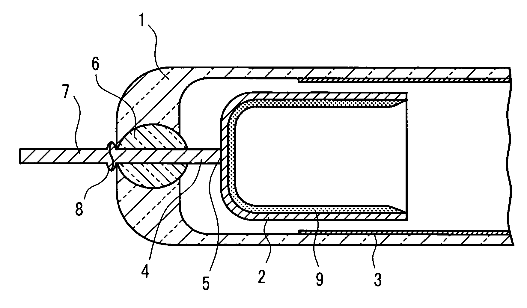
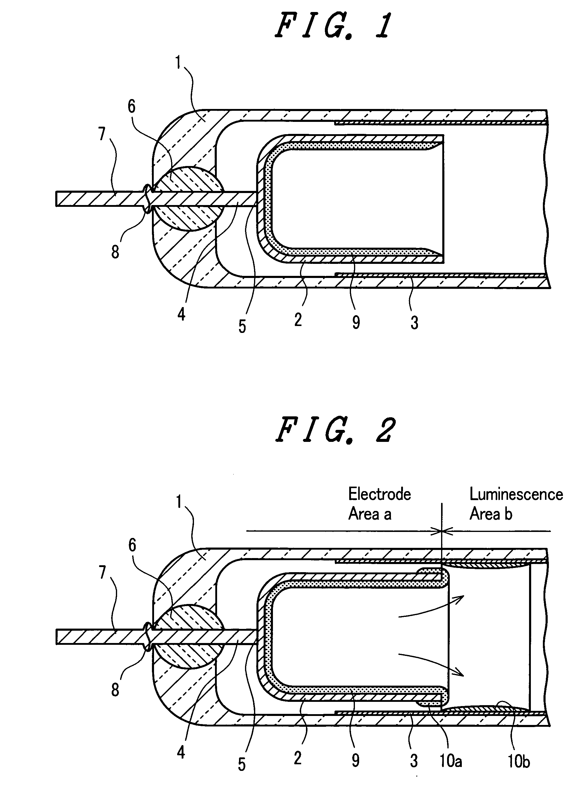
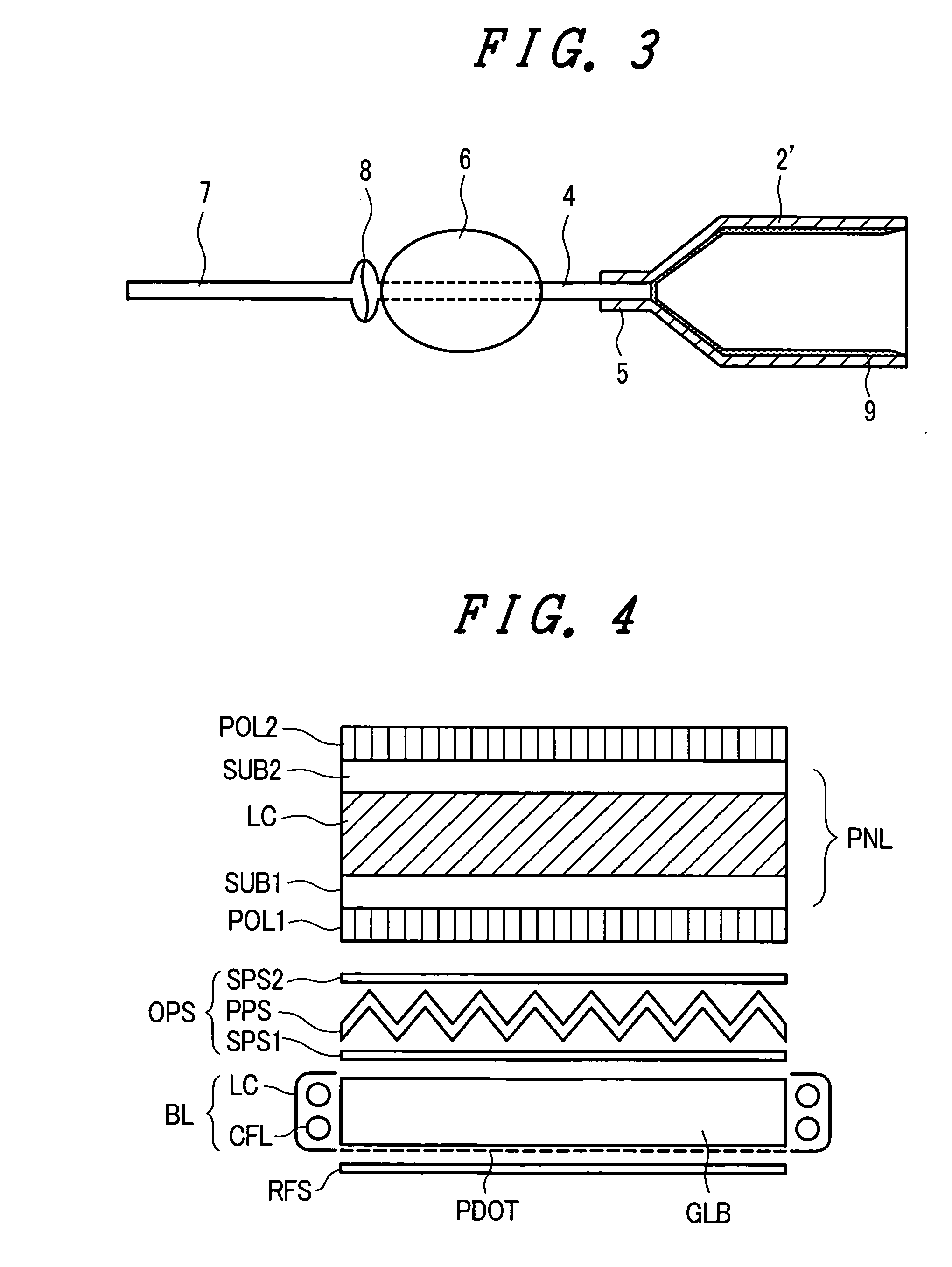
[0024]FIG. 1 is a cross-sectional view of an essential part showing the constitution according to one embodiment of a cold cathode fluorescent tube according to the present invention. The cold cathode fluorescent tube is configured such that electrodes 2 are arranged in the inside of both ends of a light transmitting glass tube 1 which constitutes an outer sheath tube, wherein the electrodes 2 face each other in an opposed manner. In FIG. 1, only one end portion of the cold cathode fluorescent tube is shown.
[0025] A phosphor layer 3 is applied to an inner wall surface of the glass tube 1 by coating and the electrodes 2 are formed into a cup-shape by a press forming method using a nickel material, wherein an opening portion which is formed at one end of the electrode 2 is directed to or faces a main discharge region (a region between b...
PUM
 Abstract
Description
Claims
Application Information
 - R&D
- Intellectual Property
- Life Sciences
- Materials
- Tech Scout
- Unparalleled Data Quality
- Higher Quality Content
- 60% Fewer Hallucinations
Browse by: Latest US Patents, China's latest patents, Technical Efficacy Thesaurus, Application Domain, Technology Topic, Popular Technical Reports.
© 2025 PatSnap. All rights reserved.Legal|Privacy policy|Modern Slavery Act Transparency Statement|Sitemap|About US| Contact US: help@patsnap.com


