Input protection circuit

a protection circuit and input technology, applied in the field of input protection circuits, can solve the problems of large voltage drop of internal impedance rs inside the thermopile, temperature measurement error, and internal impedance drop of internal impedance,

Inactive Publication Date: 2005-01-27
DENSO CORP
View PDF11 Cites 17 Cited by
  • Summary
  • Abstract
  • Description
  • Claims
  • Application Information

AI Technical Summary

Benefits of technology

[0027] Therefore, the input protection circuit can be utilized effectively as the input protection circuit to protect non-inverted amplifier, especially when the operational amplifier is implemented by a MOS input type, from the excessive voltage, because the characteristics of the input bias being nearly equal zero can be maximized and the MOS input operational amplifier which is more vulnerable to the dielectric breakdown can securely be protected from the excessive voltage.

Problems solved by technology

When an excessive voltage such as an ESD (Electro Static Discharge) is applied to the external terminals of the IC, the internal element of the IC is susceptible and may be broken.
However, although the input protection circuit 110 protects the non-inverted amplifier from an excessive voltage, a leakage current from diodes D11 and D12 causes another leakage current from the thermopile 11 to the output amplifier 100, which results in both a large voltage drop by the internal impedance Rs inside the thermopile and a temperature measurement error.
Therefore, this leakage current results in a voltage drop by the internal impedance Rs in the thermopile 11.

Method used


Image

  • Input protection circuit
  • Input protection circuit
  • Input protection circuit

Examples


Embodiment Construction

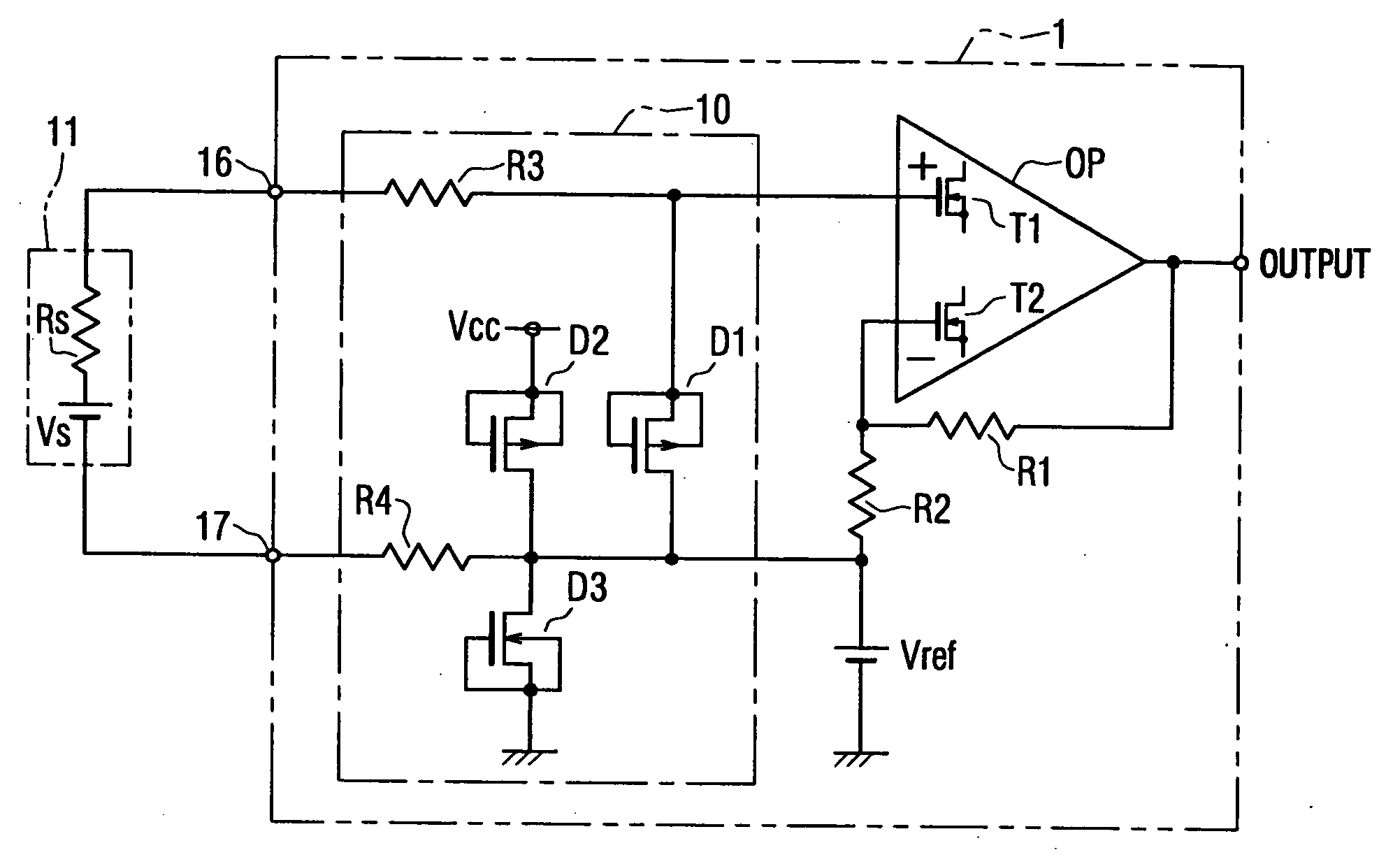
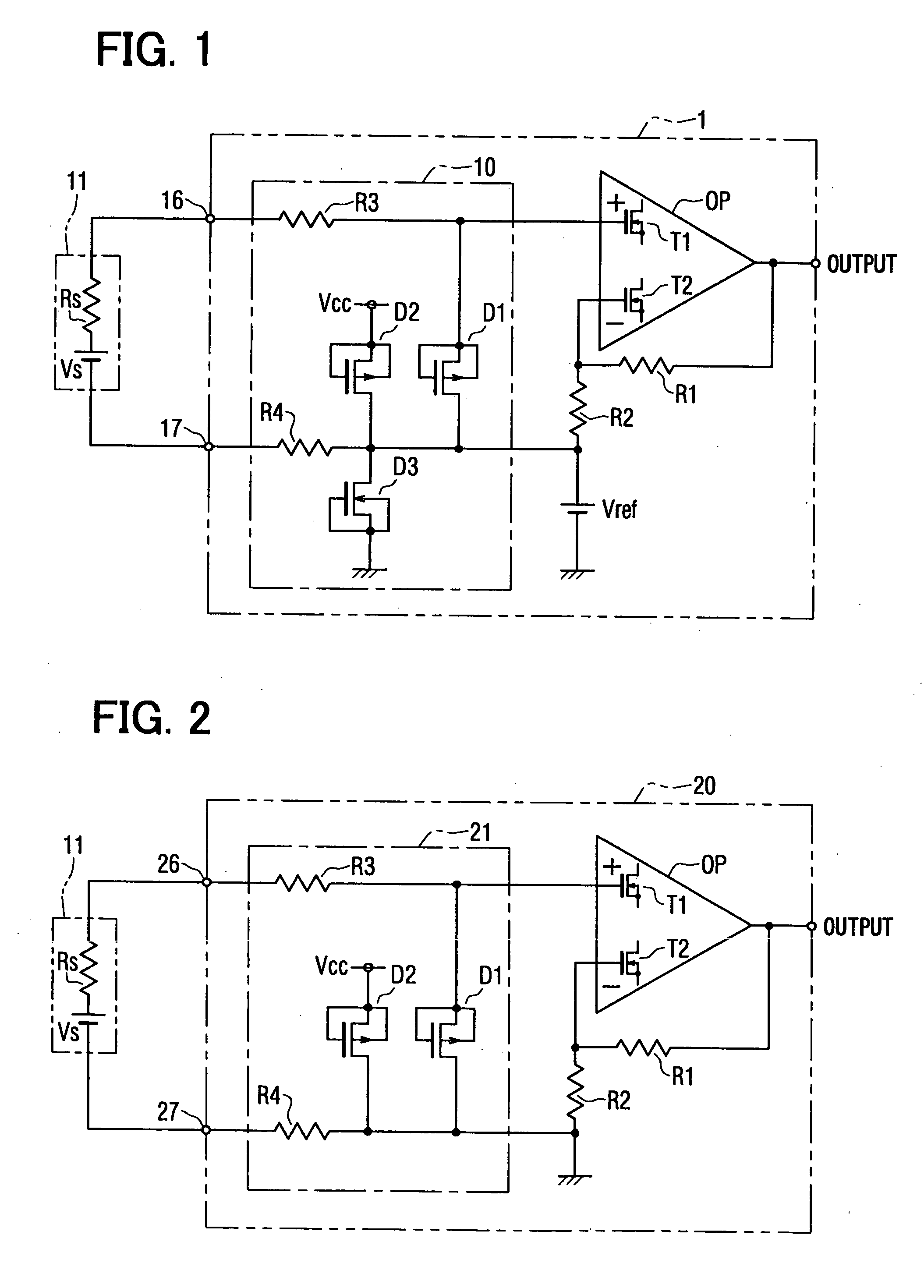
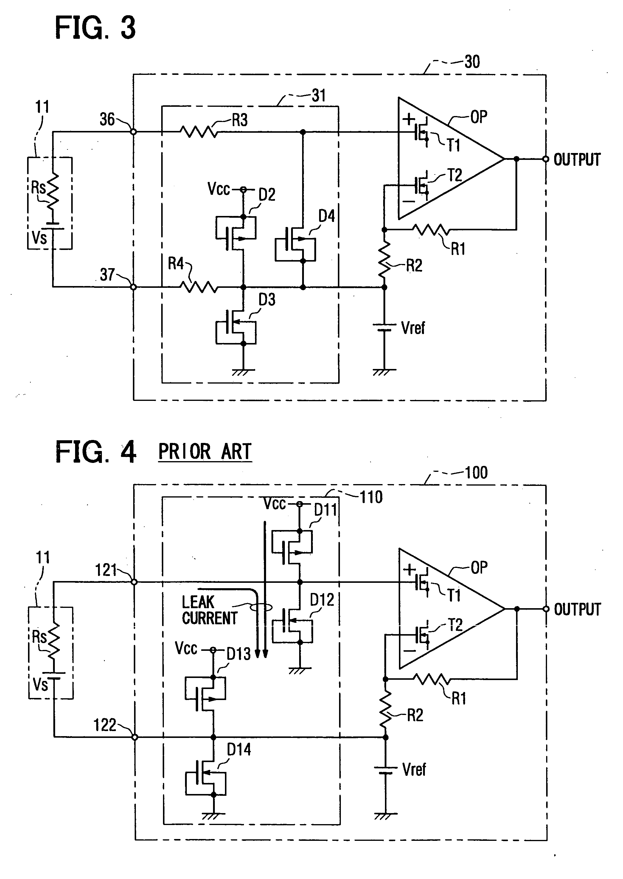
[0033] First, as shown in FIGS. 1-4, a schematic diagram of an input protection circuit is comprised of output amplifiers 1, 20, 30, 100, input protection circuits 10, 21, 31, 110, a thermopile 11, signal input terminals (+) 16, 26, 36, signal input terminals (−) 17, 27, 37, diodes D1, D2, D3, D4, an operational amplifier OP, resistors R1, R2, protection resistors R3, R4, and MOS type transistors T1, T2.

[0034] The preferred embodiment of the present invention is described based on the drawings. FIG. 1 shows a circuit diagram of an output amplifier according to a preferred embodiment. The output amplifier 1 is for amplifying the input received from a thermopile 11 (sensor signal Vs) and sending an output to an external circuit (not shown) after amplification, in a manner similar to the conventional output amplifier 100 in FIG. 4. The operational amplifier OP, a non-inverted amplifier comprised of a resistor R1 and R2, and an input protection circuit 10 are all preferably incorporate...


PUM


Abstract

An input protection circuit installed within a non-inverted amplifier includes a first diode with one end electrically connected to the non-inverted input terminal of the non-inverted amplifier and the other end electrically connected to the base voltage and a second diode having a cathode electrically connected to a power voltage of the non-inverted amplifier and an anode connected to the base voltage.

Description

CROSS REFERENCE TO RELATED APPLICATION [0001] This application is based upon, claims the benefit of priority of, and incorporates by reference the contents of, Japanese Patent Application No. 2003-277579 filed on Jul. 22, 2003. FIELD OF THE INVENTION [0002] This invention relates to an input protection circuit to prevent a non-inverted amplifier from external surge voltage. BACKGROUND OF THE INVENTION [0003] Conventionally, an operational amplifier is used as an amplifier to amplify a signal from a signal source that has a large internal impedance such as, for example, a thermopile or a semiconductor pressure sensor. A non-inverted amplifier has a large input impedance, and a leakage current from the signal source to the non-inverted amplifier is almost equal to zero. Thus, the signal level of the signal source is preserved and applied to the non-inverted input terminal in almost its original value. Therefore, this type of non-inverted amplifier is suitable for amplifying a signal f...

Claims


Application Information

Patent Timeline
Patent Type & Authority Applications(United States)
IPC IPC(8): H01L21/822H01L27/04H03F1/52
CPCH03F1/523
Inventor TANIZAWA, YUKIHIKO
Owner DENSO CORP
Why Eureka
Try Eureka