Dielectric antenna module

Inactive Publication Date: 2005-01-27
UBE IND LTD
View PDF6 Cites 19 Cited by
  • Summary
  • Abstract
  • Description
  • Claims
  • Application Information

AI Technical Summary

Benefits of technology

[0009] An object of the present invention is to provide a dielectric antenna module in which its height when mounted is small, the interference

Problems solved by technology

On the other hand, in case of card-shaped communication modules and the like used for data conication using mobile phones or personal copputers, there is a tendency that they are made thinner and smaller.
However, it is known in general that reducing the thickness of such an antenna element may bring a

Method used


Image

  • Dielectric antenna module
  • Dielectric antenna module
  • Dielectric antenna module

Examples


Example

[0041] Hereinafter, embodiments of the present invention will be described in detail with reference to drawings. In the drawings, the same reference numerals denote members or parts having the same or similar functions, respectively.

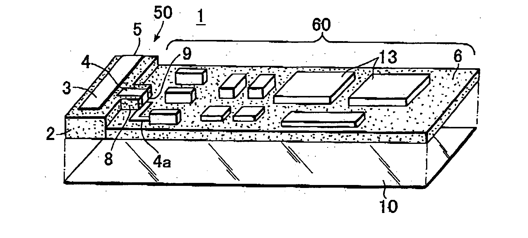
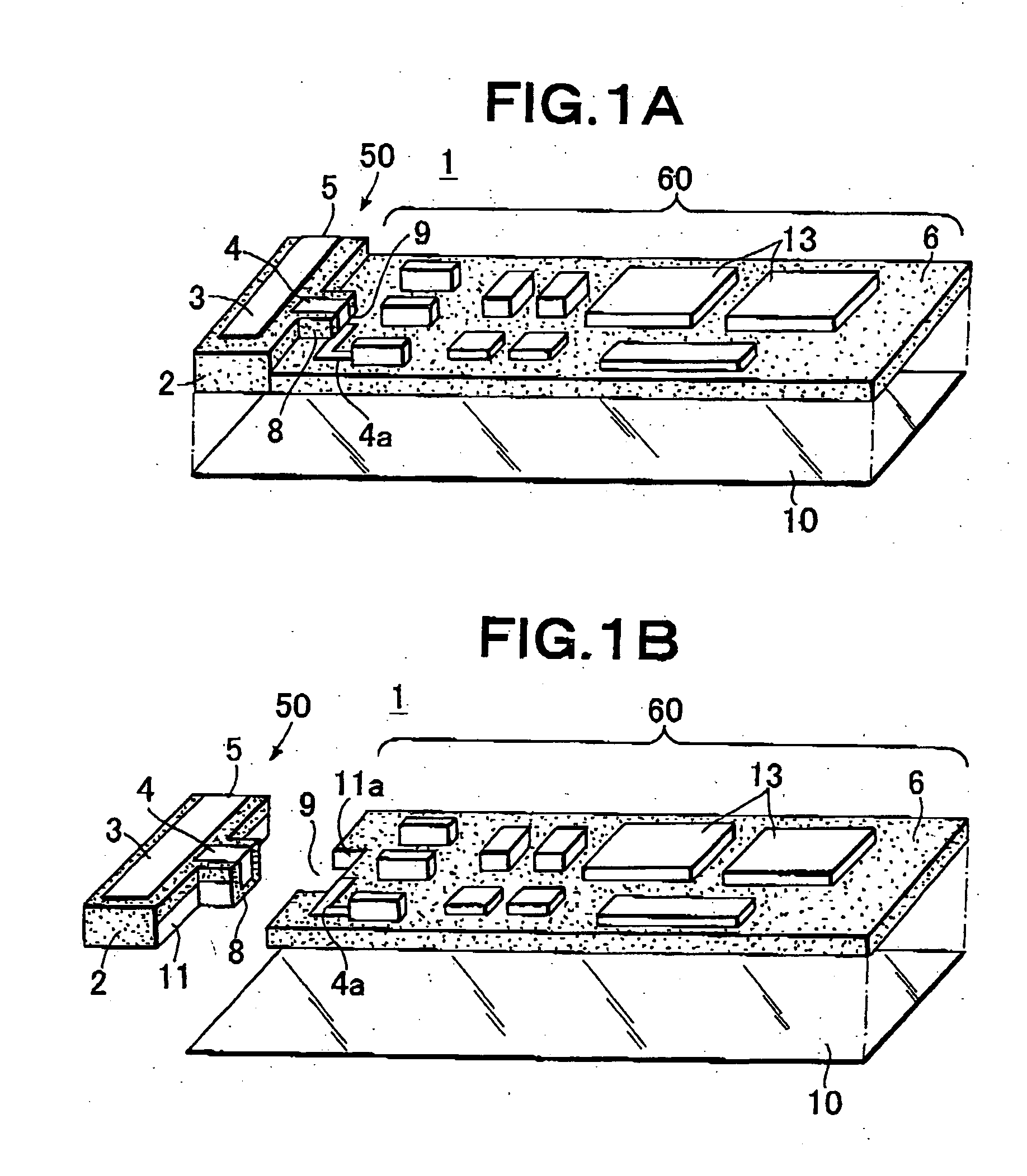
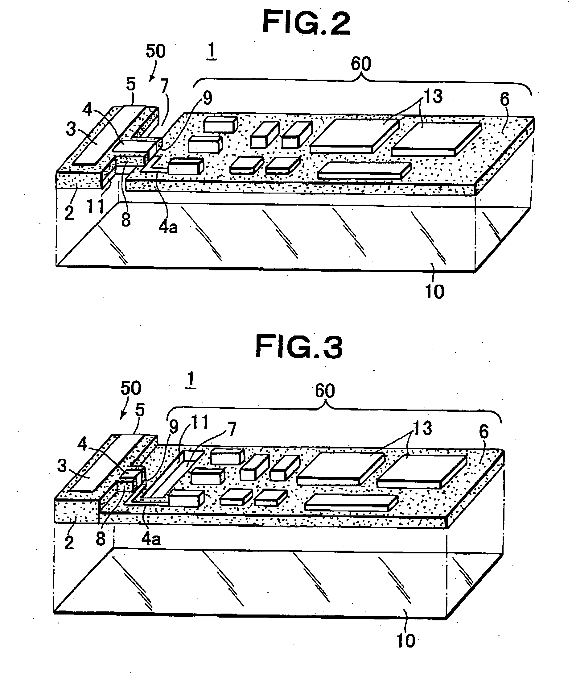
[0042]FIGS. 1A and 15 are exploded perspective views showing an embodimet of a dielectric antenna module 1, in which an antenna element unit 50 including an antenna element 5 in which a radiation electrode 3 and a signal line 4 are formed on a dielectric substrate (first dielectric substrate) 2, and a module substrate unit 60 including a module substrate (second dielectric substrate) 6 on which a signal processing circuit is formed, are disposed and connected to each other so that the respective bottom faces of the antenna element unit and the module substrate unit are in a single plane.

[0043] In the antenna element unit 50, the radiation electrode 3 is formed on an upper face of the dielectric substrate 2, and the signal line 4 is formed from the uppe...


PUM


Abstract

A dielectric antenna module (1) includes an antenna element unit (50) having an antenna element (5) consisting of a radiation electrode (3) and a signal line (4) formed on a dielectric substrate (2), and a module substrate unit (60) having a signal processing circuit formed on a module substrate (6). The substrate (2,6) are arranged and connected to each other so that their bottom surfaces form a single plane. The antenna element unit (50) and the module substrate unit (60) are connected to each other by fitting a projection (8) to a recess (9) formed on and in the opposing faces of the substrates (2,6). On the projection (8) and in the recess (9), signal lines (4,4a) are formed, respectively, and on the opposing faces of the substrates (2,6), ground electrodes (11,11a) are formed. When the projection and recesses are engaged, the signal lines (4,4a) are connected to each other and the ground electrodes (11,11a) are connected to each other. A base film (10) where a ground electrode is formed is attached to the bottan surface of the substrates (2,6).

Description

TECHNICAL FIELD [0001] The present invention relates to a dielectric antenna module, suitable for microwave and millimeter wave, in which an antenna element in which a plane radiation electrode is formed on a dielectric substrate, and a module substrate on which a signal processing circuit is formed, are connected to each other. Also, the present invention relates to a dielectric antenna modile, suitable for microwave and millimeter wave, in which an antenna unit and a signal processing circuit unit are formed on a single dielectric substrate. In particular, a dielectric antenna module of the present invention is most suitable for Bluetooth or the like. BACKGROUND ART [0002] In recent years, in addition to mobile communication systems, in particular, communication systems using mobile phones or mobile terminals, systems for dealing with information ccmmunication such as Bluetooth is being rapidly put to practical use. Particularly in Bluetooth, because a communcation module constitu...

Claims


Application Information

Patent Timeline
IPC IPC(8): H01Q1/24G08B15/00H01Q1/38H01Q9/04H01Q21/00H01Q23/00H05K1/02H05K1/14H05K1/16
CPCH01L2223/6677H01Q1/241H01Q1/38H01Q9/0407H01Q21/0025H05K2203/167H05K1/0218H05K1/141H05K1/142H05K1/16H05K2201/09145H01Q23/00
Inventor OYAMA, RYUJIYASUMURA, MORITO
Owner UBE IND LTD
Why Eureka
Try Eureka