Transflective liquid crystal display and method of fabricating the same

a liquid crystal display and reflector technology, applied in optics, instruments, electrical equipment, etc., can solve the problems of increasing power consumption of backlight, affecting the visibility of display, and consuming 50% or more of the total power consumed by the lcd device, so as to improve the aperture ratio, simplify the rubbing process, and high contrast ratio and brightness

Active Publication Date: 2005-01-27
LG DISPLAY CO LTD
View PDF6 Cites 27 Cited by
  • Summary
  • Abstract
  • Description
  • Claims
  • Application Information

AI Technical Summary

Benefits of technology

[0033] Embodiments of the present invention provide a transflective LCD display and a method of fabricating the same achieving a high contrast ratio and brightness. The embodiments provide a transflective LCD display and a method of fabricating the same improving an aperture ratio and simplifying a rubbing process.

Problems solved by technology

However, the backlight of the transmission type LCD consumes 50% or more of the total power consumed by the LCD device.
Providing a backlight therefore increases power consumption.
The reflection type LCD using the reflection of ambient light is disadvantageous in that a visibility of the display is extremely poor when surrounding environment is dark.
Moreover in the related art transflective LCD device, since the opening and the transflective portion are relatively small and are located in the middle of the pixel region P, it is difficult to uniformly perform the rubbing process when inducing the initial alignment direction of the liquid crystals.
This prevents uniform and stable transmittance from being attained in the transflective portion.

Method used


Image

  • Transflective liquid crystal display and method of fabricating the same
  • Transflective liquid crystal display and method of fabricating the same
  • Transflective liquid crystal display and method of fabricating the same

Examples


first embodiment

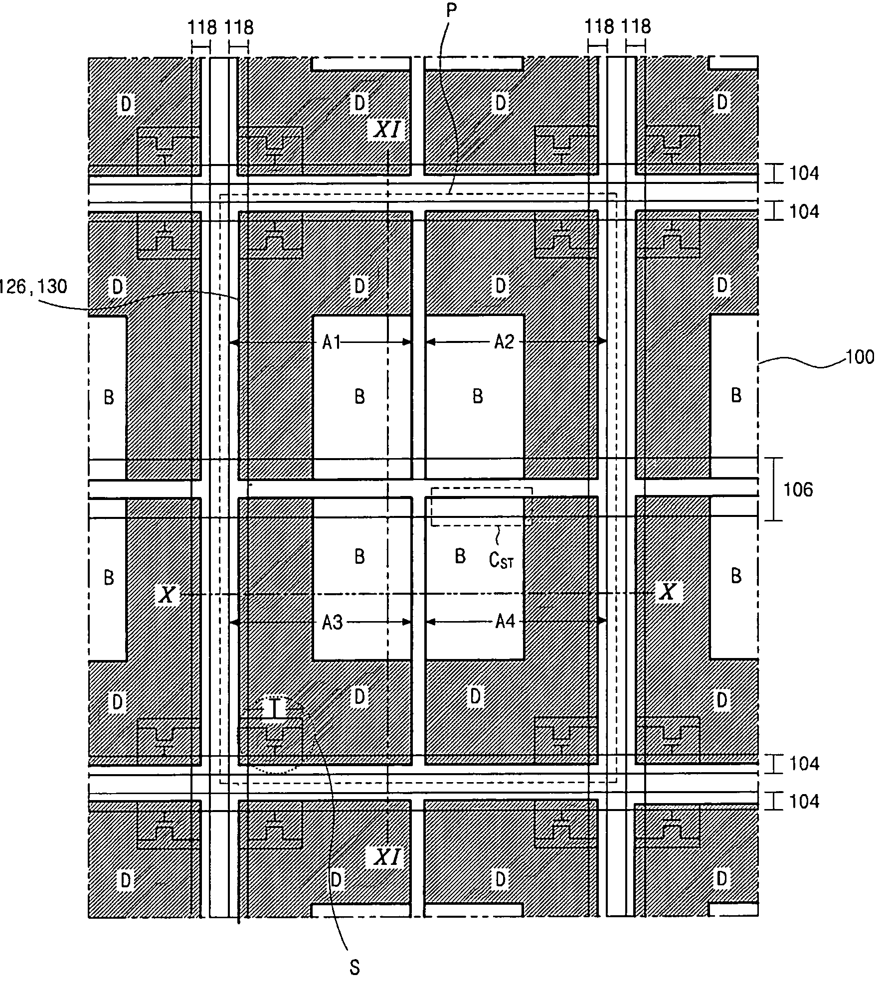
[0065]FIG. 7 is a plan view illustrating a transflective LCD device according to the present invention, and FIG. 8 is an enlarged plan view illustrating a portion S of FIG. 8.

[0066] As shown in FIG. 7, a plurality of unit pixels P is defined in a substrate 100, and each unit pixel P has first to fourth sub-pixel regions A1-A4 each of that has a transmissive portion B and a reflective portion D. Unlike the previously shown related art, the transmissive portion B is located at one corner of each of the first to fourth sub-pixel regions A1-A4. The transmissive portions B of the first to fourth sub-pixel regions A1-A4 are gathered at the center of the unit pixel P. Namely, the transmissive portions B are close together in the middle of the unit pixel P, and the reflective portions D surround the transmissive potions B in the unit pixel P.

[0067] Still referring to FIG. 7, gate lines 104 are horizontally disposed over the substrate 100, and data lines 118 are longitudinally disposed over...

second embodiment

[0090] As described before, the transmissive portions B of the first to fourth sub-pixel regions A1-A4 gather together in the center of the unit pixel P. The sub-pixel region includes the transmissive potion B at one corner thereof opposite to the thin film transistor T, and thus the transmissive portion B is located next to the other transmissive portions of the neighboring sub-pixel regions within the unit pixel P. This structure, in which the transmissive portions B are gathered, decreases the border area between the reflective portion D and the transmissive portion B within each sub-pixel region by one half compared to the related art shown in FIG. 5. Furthermore, since the transmissive portions B are disposed together in the center of the unit pixel P, the marginal value in forming the array elements is enlarged. Namely, since the border area between the reflective portion D and the transmissive portion B decreases by half compared to the related art, the aperture ratio is corr...


PUM

PropertyMeasurementUnit
heightaaaaaaaaaa
heightaaaaaaaaaa
distanceaaaaaaaaaa

Abstract

A transflective liquid crystal display includes gate and data lines perpendicular to each other and defining a plurality of unit pixels. Each unit pixel includes a plurality of sub-pixel regions, which each have a transmissive portions and a reflective portion. The transmissive portions are gathered together within each unit pixel at corners of the sub-pixel regions opposing corners in which thin film transistors near the crossings of the gate and data lines are disposed. A passivation layer covering the thin film transistors and the gate and data lines has an opening that corresponds to the transmissive portions in the unit pixel. A reflector is formed over the passivation layer in each sub-pixel region and corresponds in position to the reflective portion. A pixel electrode in each sub-pixel region contacts the thin film transistor through a contact hole in the passivation layer.

Description

[0001] This application claims the benefit of Korean Application No. 2003-0037416 filed on Jun. 11, 2003, which is hereby incorporated by reference. BACKGROUND OF THE INVENTION [0002] 1. Field of the Invention [0003] The present invention relates to a liquid crystal display, and more particularly, to a transflective liquid crystal display and method of fabricating the same. [0004] 2. Discussion of the Related Art [0005] In general, both transmission and reflection type liquid crystal displays (LCD) are used. Transmission type LCDs use internal light sources while reflection type LCDs use external light sources. The transmission type LCD has a liquid crystal display panel, which does not emit light itself, and has a backlight as a light-illuminating section. [0006] The backlight is disposed at the rear or one side of the panel. The amount of the light from the backlight that passes through the liquid crystal panel is controlled by the liquid crystal panel in order to implement an ima...

Claims


Application Information

Patent Timeline
Patent Type & Authority Applications(United States)
IPC IPC(8): G02F1/1333G02F1/1335G02F1/1343G02F1/1368
CPCG02F2001/134345G02F1/133555G02F1/134345G02F1/1335
Inventor PARK, JAE-DEOKJEOUNG, HUNHONG, SOON-KWANG
Owner LG DISPLAY CO LTD
Why Eureka
Try Eureka