Cutting insert for turning and milling

a cutting insert and milling technology, applied in the field of cutting inserts, can solve the problems of low fracture resistance, limited geometrical design, and still relatively expensive both in manufacture and in practical application

Inactive Publication Date: 2005-01-27
SANDVIK INTELLECTUAL PROPERTY AB
View PDF2 Cites 34 Cited by
  • Summary
  • Abstract
  • Description
  • Claims
  • Application Information

AI Technical Summary

Benefits of technology

[0010] Compared with this state of the art, it is the object of the present invention to provide a cutting...

Problems solved by technology

Such cutting inserts are distinguished by particular hardness and durability, but on the other hand also have a lower fracture resistance than tool steel and so, to obtain sufficient stability, are restricted with respect to their geometrical design.
Owing to their extraordinary hardness and the quality (dimensional stability and sufficient fracture resistance) of such cutting inserts which has been improved more and more in the...

Method used


Image

  • Cutting insert for turning and milling
  • Cutting insert for turning and milling
  • Cutting insert for turning and milling

Examples


Embodiment Construction

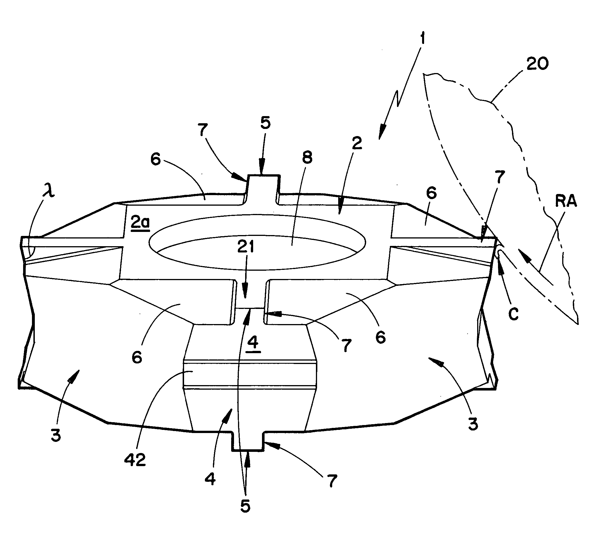
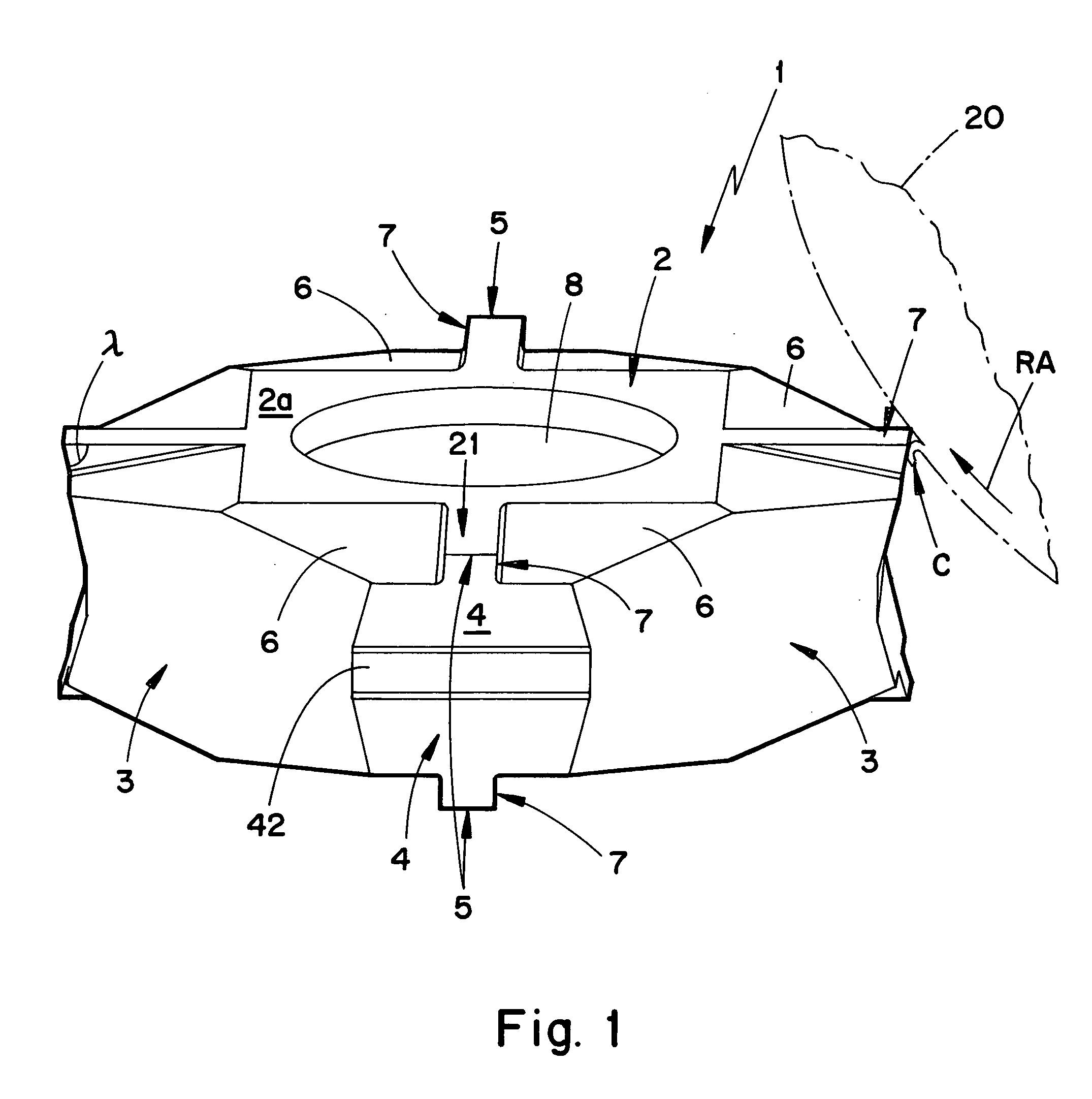
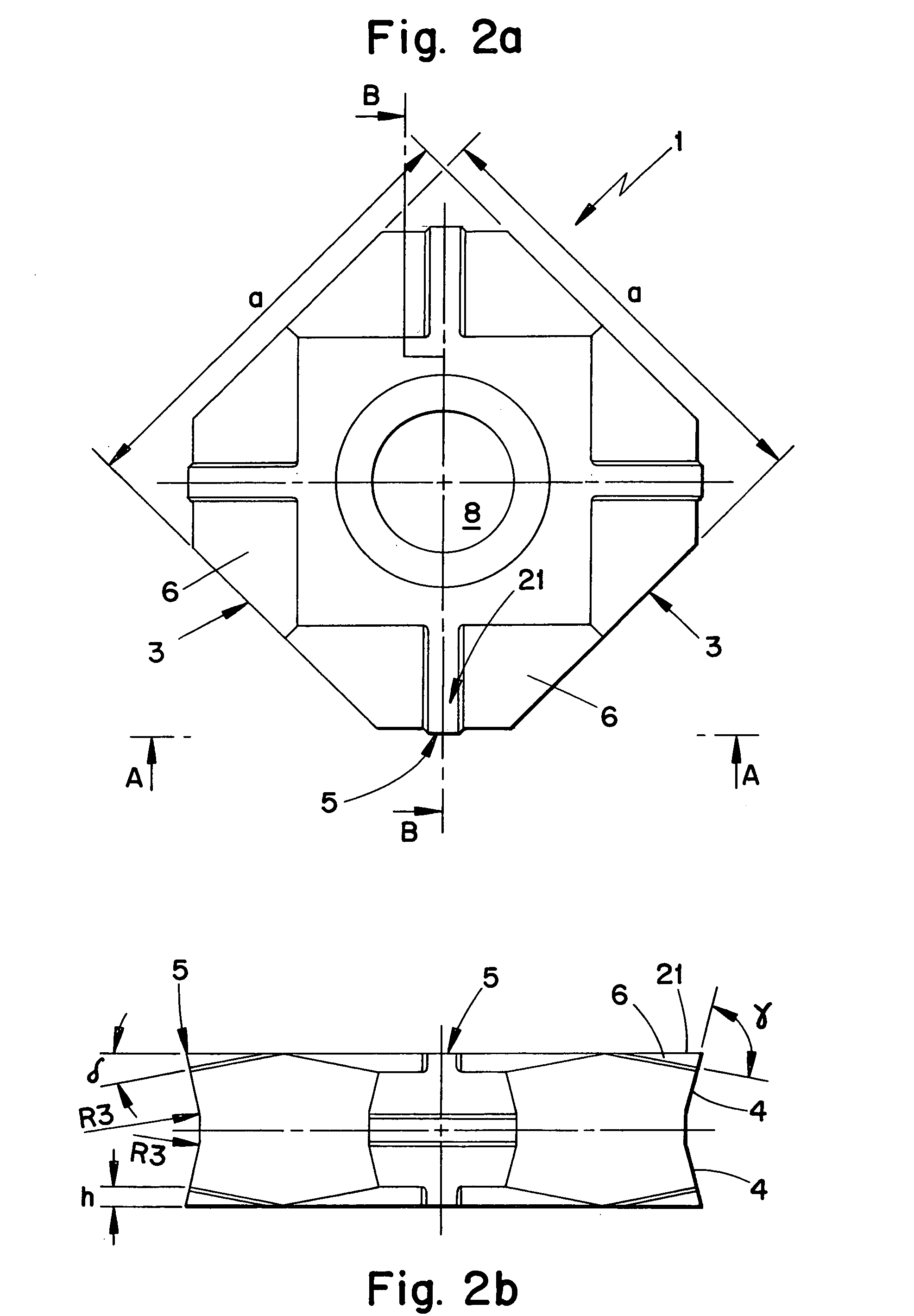
[0052] In FIG. 1 and in FIGS. 2a, 2b and 3a-3c can be seen the cutting insert 1 which has the basic shape of a polygonal parallelepiped.

[0053] The cutting insert has first and second (i.e., upper and lower) main faces 2, 2′ interconnected by a side face structure 3A to form therewith a peripheral edge 5A. The plane of the upper main face 2 is substantially defined by a central contact face 2a which surrounds a central fastening bore 8. The upper main face 2 includes branch surfaces 21, each of which projects from the center of one side of the contact face 2a. The branch surfaces define relief surfaces to respective narrow cutting edges 5 formed at the end of the branch surfaces. The branch surfaces have been made as a result of the fact that the upper face 2 on both sides of such a branch surface 21 has recesses, preferably in the form of flattened portions 6 which are declined at an angle δ (FIG. 2b) of between 10° and 25° relative to the central face 22, so that in the middle bet...


PUM

PropertyMeasurementUnit
Angleaaaaaaaaaa
Angleaaaaaaaaaa
Angleaaaaaaaaaa

Abstract

A cutting insert comprises first and second polygonally-shaped main faces arranged substantially parallel to one another, and a side face structure interconnecting the first and second main faces to define a peripheral edge. At least the first main face includes at least one projection extending to the peripheral edge, the projection formed by: a portion of the first main surface (defining a relief surface), a portion of the side face structure (defining a rake surface), and a portion of the peripheral edge (defining a cutting edge). The insert includes support surfaces defined by a portion of the second main face, and by portions of the side surface structure other than the rake surface.

Description

[0001] This application claims priority under 35 U.S.C. §119 to Patent Application Serial No. 103 26 662.3 filed in Germany on Jun. 11, 2003, the entire content of which is hereby incorporated by reference. BACKGROUND OF THE INVENTION [0002] The present invention concerns a cutting insert, preferably for turning and / or milling, in the form of a polyhedron with at least two substantially parallel main faces each with a polygonal contour and with a peripheral side wall consisting of several side faces which connect the parallel main faces to each other. At the junction of at least some of the partial side faces with at least one of the main faces are formed cutting edges which have a presettable profile which is defined by the structuring of the upper and / or lower main face and / or of the side faces in the region of the cutting edge. [0003] Corresponding cutting inserts have already been known for a long time. These cutting inserts are typically made of hard metal and are first pressed...

Claims


Application Information

Patent Timeline
IPC IPC(8): B23B27/16B23C5/08B23C5/02B23C5/10B23C5/20
CPCB23B27/1614Y10T407/1942B23B2200/0457B23B2200/081B23B2200/085B23B2200/161B23B2200/163B23B2200/3627B23B2200/3663B23B2215/16B23B2220/12B23C5/08B23C2200/367Y10T407/2274Y10T407/23Y10T407/1962B23B2200/0404B23C5/02B23C5/10B23C5/20B23B27/16
Inventor WERMEISTER, GUNTER
Owner SANDVIK INTELLECTUAL PROPERTY AB
Why Eureka
Try Eureka