DC offset cancellation in a zero if receiver

a zero-if receiver and dc offset technology, applied in the field of methods and apparatus for correcting dc offset problems, can solve the problems of dc offset errors in the system, dc offset errors that profoundly degrade the snr after demodulation, and amplifiers used in the i and q branches to saturate, so as to minimize the effect of dc offset errors

Active Publication Date: 2005-01-27
MAXIM INTEGRATED PROD INC
View PDF14 Cites 20 Cited by
  • Summary
  • Abstract
  • Description
  • Claims
  • Application Information

AI Technical Summary

Benefits of technology

[0005] The instant invention uses an automatic gain controller AGC and a digital signal processor along with zero IF transceiver circuitry to create I and Q signals to process and remove DC offset signals in acceptable time periods. Using a combination of techniques such as AC and DC coupling, automatic gain control, and digital signal processing, the DC offsets are removed to insignificant levels. The main features or steps of the invention are: 1) dynamically changing the cut off frequency of an AC coupling stage; 2) computing a DC signal error over a time period in which the I and Q signals complete a single or multiple cycles, 3) subtracting the estimated DC errors from the I and Q signals, and 4) high-pass filtering the resultant signal so that residual DC errors are removed. The implementation and timing of these steps allows for DC offset control that is far superior to prior art systems.
[0007] In a third embodiment, the transceiver frequency error is further removed in the receiver by changing the voltage controlled oscillator crystal (VCXO) frequency that is used for the local oscillator (LO) frequency synthesizer. This also ensures that the effect of the DC offset error is minimized after demodulating an OFDM signal.

Problems solved by technology

Therefore each of these DC coupled stages introduces a DC offset error into the signal.
In an orthogonal frequency division multiplexing (OFDM) system, a difference between the local oscillator (LO) frequency and the incoming signal frequency causes DC offset errors within the system to profoundly degrade the SNR after demodulation.
These unwanted DC errors may also cause the amplifiers used in the I and Q branches to saturate.
Once the amplifier is in a saturated state, the received data signal cannot be processed and amplified correctly so the received data signal is lost.
Prior art attempts to deal with the above problems have been only semi-successful.
The reduced DC offset is still too high for OFDM systems and takes too long to settle.
As mentioned above, with an increase in data speeds, this prior art system is not useable in today's transceiver environments.
All known prior art techniques used to reduce these DC offset errors have drawbacks in one form or another.
For example, AC coupling signals with high frequency cut off values may reduce response time, but has an unacceptable signal to noise ratio or an unacceptable effect on the signal itself Further, automatic gain control is also only useable when the DC offset level is very small.
The end result is that these DC offset values can not be reduced in an acceptable amount of time.

Method used


Image

  • DC offset cancellation in a zero if receiver
  • DC offset cancellation in a zero if receiver
  • DC offset cancellation in a zero if receiver

Examples


Embodiment Construction

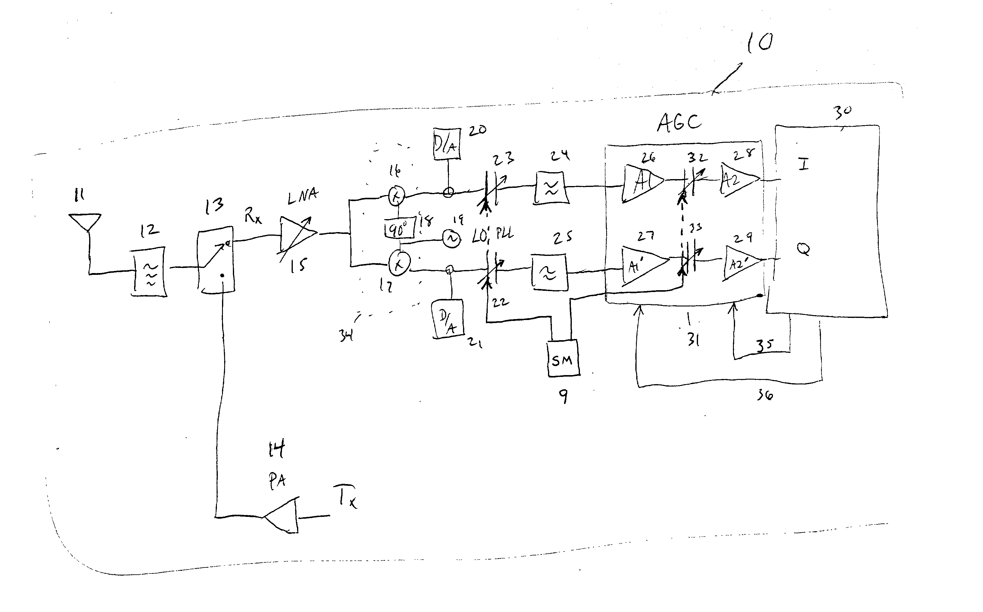
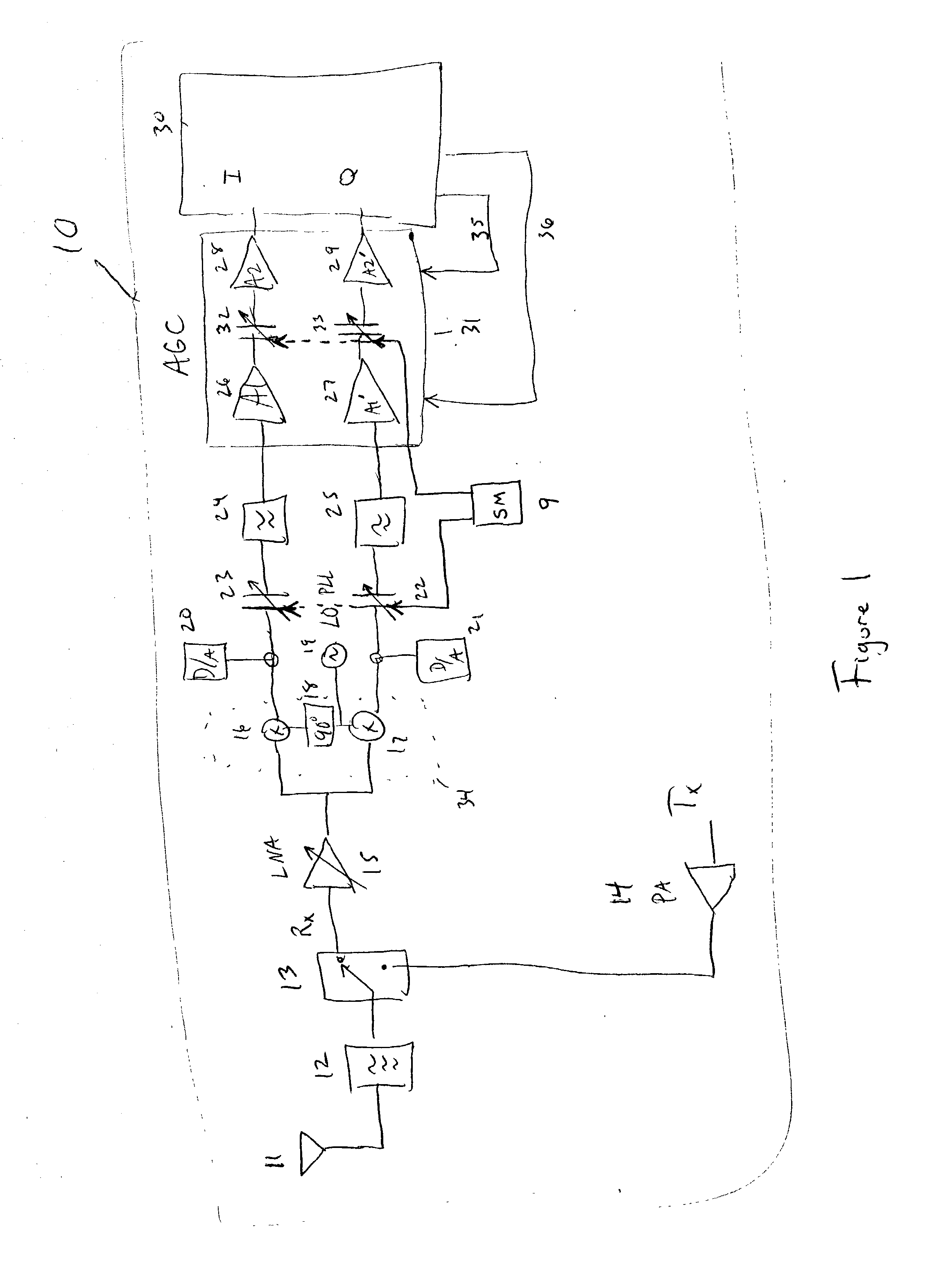
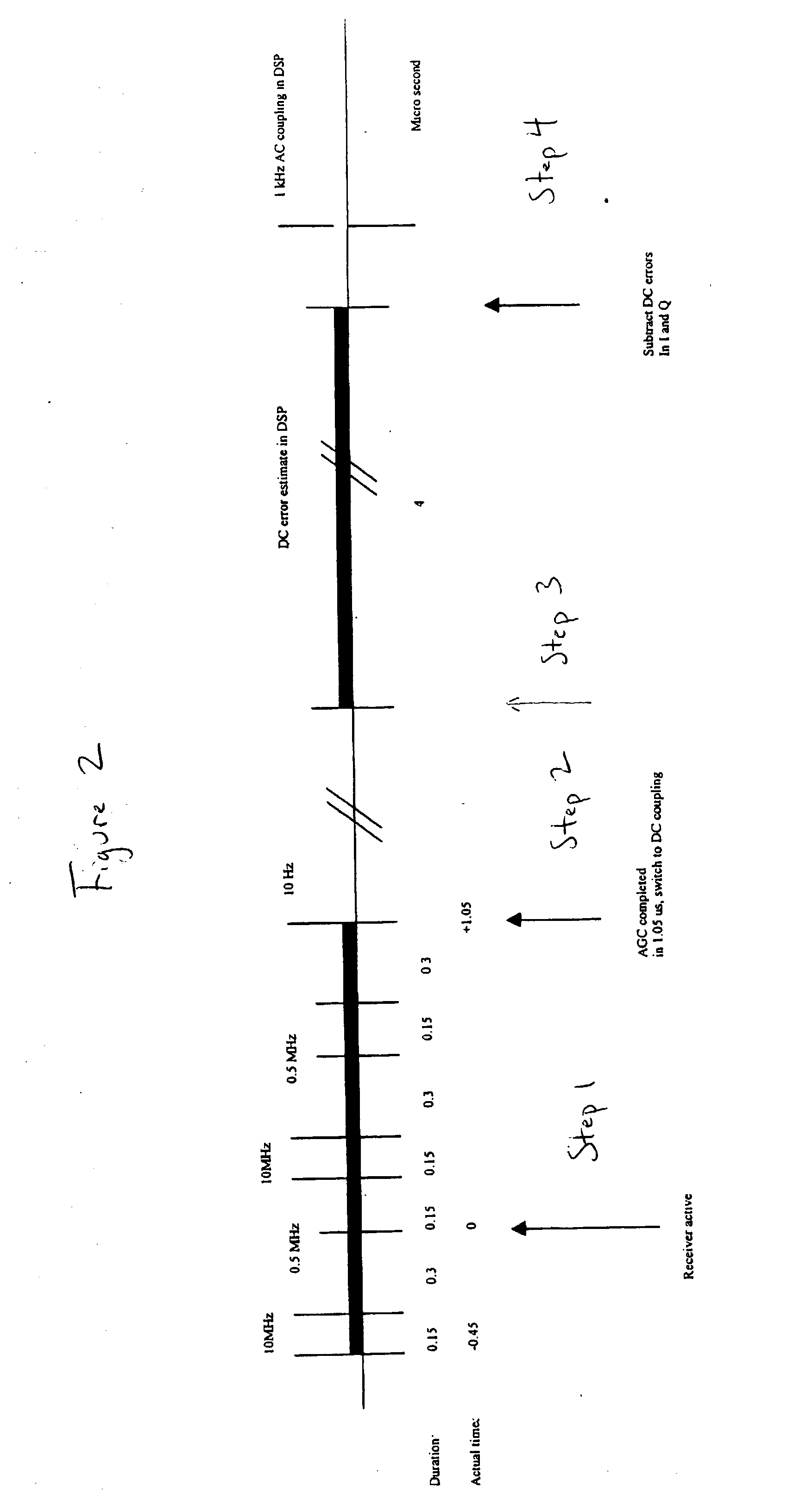
[0012] Using a combination of techniques such as AC and DC coupling, automatic gain control, and digital signal processing, the DC offsets are removed to insignificant levels. The main features or steps of the invention are dynamically changing the cut off frequency of an AC coupling stage; computing a DC signal error over a time period in which the I and Q signals complete a single or multiple cycles, subtracting the estimated DC errors from the I and Q signals, and high-pass filtering the resultant signal so that residual DC errors are removed. The implementation and timing of these steps allows for DC offset control that is far superior to prior art systems.

[0013] In a second embodiment a D / A converter is used in each of the I and Q branches to significantly reduce the DC offset, and the steps as mentioned above are followed. The DSP does a course DC correction with the D / A converter, and maintains a list of correction values for all combinations of antenna diversity and LNA amp...


PUM


Abstract

This invention describes how to quickly cancel DC offsets that are present in the two quadrature paths of a zero intermediate frequency transceiver. Previously known techniques are not suitable for the 5 GHz WLAN standards because of the very short transmit to receive turn around times and extraordinarily large dc offsets in these systems. This invention solves the above problems. The present invention uses both AC and DC coupling along with automatic gain control techniques to remove unwanted DC offsets within an acceptable time period. The invention further uses a digital signal processor to estimate and subtract out the DC offset errors using time averaged signals. The digital signal processing circuit is capable of further AC filtering and Analog to Digital conversions.

Description

BACKGROUND OF INVENTION [0001] The invention relates to a method and apparatus for correcting DC offset problems found in high-speed transceiver systems. [0002] Conventional transceiver systems commonly must switch back and forth between transmit and receive modes. As the speed of data transmission increases, the time allowed for switching between the Transmit (Tx) and Receive (Rx) modes becomes smaller. One conventional type of receiver is known as a Direct Conversion zero intermediate frequency (IF) receiver. In this type of receiver a local oscillator is tuned to the carrier frequency of the incoming signal. These types of receivers commonly have multiple stages in which the incoming signal is down converted and processed using a local oscillator (LO) circuit. These IF type receivers create in phase (I) and 90 degrees out of phase quadrature (Q) signals from the received signal. Large DC offsets are produced in the down converter outputs of Zero IF receivers due to LO leakage at ...

Claims


Application Information

Patent Timeline
Patent Type & Authority Applications(United States)
IPC IPC(8): H04B1/30
CPCH04B1/30
Inventor MOHINDRA, RISHI
Owner MAXIM INTEGRATED PROD INC
Why Eureka
Try Eureka