Method and apparatus for target position verification

a technology of target position and target position, applied in the field of target position verification, can solve the problems of increased risk of damaging healthy tissue, sensitive structures, and unhealthy tissue surrounding, and achieve the effect of preventing healthy tissue surrounding

Active Publication Date: 2005-01-27
BEST MEDICAL INT
View PDF7 Cites 74 Cited by
  • Summary
  • Abstract
  • Description
  • Claims
  • Application Information

AI Technical Summary

Benefits of technology

[0021] The target alignment system and methods have the advantages of preventing healthy tissue surrounding the tumor, or healthy organs or sensitive structures located adjacent the tumor, from being exposed to an undesired amount of radiation, and permits the verification that the target with respect to the radiation therapy treatment device conforms to the desired position of the target in the radiation treatment plan, and, if not, adjustment of the position thereof.

Problems solved by technology

It is believed that a vast majority of tumors can be eradicated completely if a sufficient radiation dose is delivered to the tumor volume; however, complications may result from use of the necessary effective radiation dose, due to damage to healthy tissue which surrounds the tumor, or to other healthy body organs located close to the tumor.
A basic problem in radiation therapy is knowing where the target, or tumor, is located at the time the radiation therapy treatment is occurring.
If the position of the target is not the same as it was at the time the treatment plan was determined, the dose of radiation may not be delivered to the correct location within the patient's body.
Since patients are not always positioned properly on the treatment table of the radiation therapy device, which may be a linear accelerator or a cobalt unit, and since organs of a patient may move within the patient from day to day, the target may not be positioned at the exact location where the radiation therapy plan has assumed it would be located.
A disadvantage of such conventional radiation therapy plans is that there is a major concern associated with increasing the volume of tissue which is treated, to insure that the actual target to be treated receives the desired dose of radiation.
Because some healthy tissue surrounds the target to be treated, or healthy organs, or sensitive structures, lie adjacent to the target to be treated, delivering the maximum desired radiation dose to this larger volume of tissue may occur and increase risk of damaging healthy tissue, healthy organs, or sensitive structures.
Due to this increased risk, some Oncologists will deliver a smaller radiation dose to the larger treatment volume, which is safer for the healthy tissue, with the potential disadvantage of underdosing the target to be treated.
However, ultrasound has some significant image capture limitations.
The ultrasound image itself is by its nature grainy, and it is very common for it to be difficult, especially for the less than expert user, to identify information from a static image.
In contrast, when the sonographer captures a still, or static, image for them to take home and show the family, it is often impossible to identify the features in the still, or static, image that were so obvious in the live, or dynamic image.
For a variety of reasons, use of static ultrasound images may not be as easy to use when compared to viewing the live, dynamic ultrasound.

Method used


Image

  • Method and apparatus for target position verification
  • Method and apparatus for target position verification
  • Method and apparatus for target position verification

Examples


Embodiment Construction

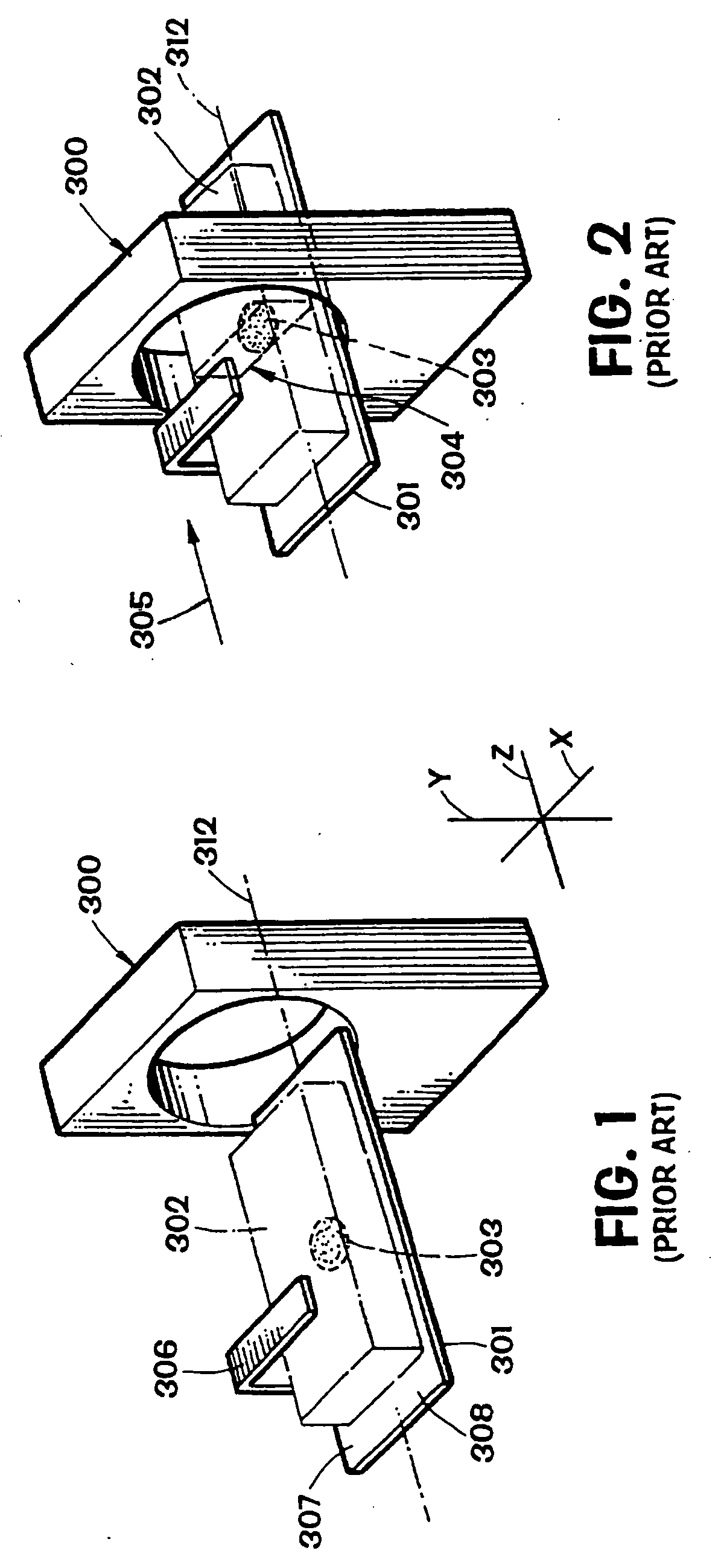
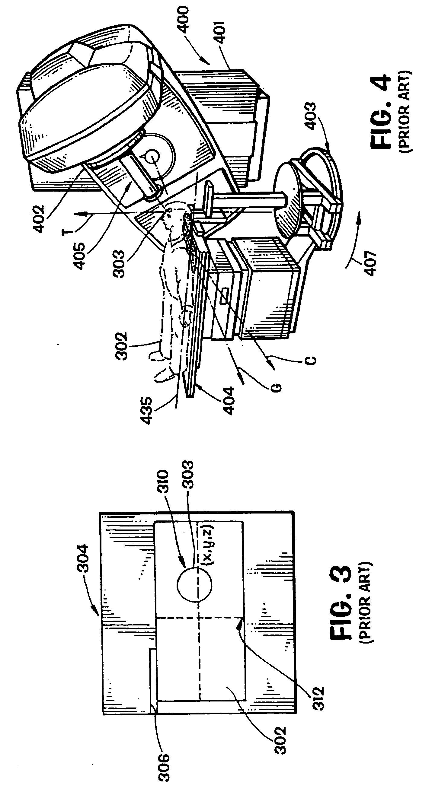
[0032] With reference to FIG. 1, a conventional imaging device 300 is schematically shown and includes a conventional imaging table 301, upon which is disposed a patient 302 having a tumor, or target, 303 within the patient's body 302. As previously discussed, the use of the term “target” throughout this specification, including the claims, includes, as appropriate, a tumor or an organ, or portion thereof, to be treated, or an organ, sensitive structure, or portion thereof, which is not to be treated in the radiation therapy plan. Imaging device 300 may be a computerized tomographic (“CT”) scanning device, as illustrated in FIG. 1, or may alternatively be a magnetic resonance (“MR”) imaging device, as are known in the art. CT scanning devices, such as imaging device 300, produce an image representing a “slice” of body tissue 304 (shown in phantom lines in FIG. 2), one such slice being illustrated in FIG. 3. A plurality of images, or diagnostic images, 304 are obtained by the imaging...


PUM


Abstract

A system and method for aligning the position of a target within a body of a patient to a predetermined position used in the development of a radiation treatment plan can include an ultrasound probe used for generating live ultrasound images, a position sensing system for indicating the position of the ultrasound probe with respect to the radiation therapy device, and a computer system. The computer system is used to display the live ultrasound images of a target in association with representations of the radiation treatment plan, to align the displayed representations of the radiation treatment plan with the displayed live ultrasound images, to capture and store at least two two-dimensional ultrasound images of the target overlaid with the aligned representations of the treatment plan data, and to determine the difference between the location of the target in the ultrasound images and the location of the target in the representations of the radiation treatment plan.

Description

RELATED APPLICATION [0001] This application claims the benefit of U.S. Provisional Patent Application Ser. No. 60 / 416,635, titled “Method And Apparatus For Target Position Verification,” filed Oct. 7, 2002.BACKGROUND OF THE INVENTION [0002] 1. Field Of The Invention [0003] The invention relates to a method and apparatus for verifying and aligning the position of a target to be treated by a radiation therapy device operating in accordance with a radiation therapy plan. [0004] 2. Description of the Related Art [0005] Modern day radiation therapy of cancerous tumors has two goals: eradication of the tumor and avoidance of damage to healthy tissue and organs present near the tumor. It is believed that a vast majority of tumors can be eradicated completely if a sufficient radiation dose is delivered to the tumor volume; however, complications may result from use of the necessary effective radiation dose, due to damage to healthy tissue which surrounds the tumor, or to other healthy body ...

Claims


Application Information

Patent Timeline
Patent Type & Authority Applications(United States)
IPC IPC(8): A61B8/08A61N5/10
CPCA61N5/1049A61B8/08A61B8/4245A61B8/4263
Inventor SCHERCH, JOHN DAVID
Owner BEST MEDICAL INT
Why Eureka
Try Eureka