Method and system for delivering an implant utilizing a lumen reducing member

a technology of lumen reducing member and implant, which is applied in the field of implantable devices, can solve the problems of significant bleeding, serious injury and death, and the difficulty of accessing and treating intracranial aneurysms, and achieves the effects of improving the quality of life, and improving the safety of patients

Inactive Publication Date: 2005-01-27
STRYKER EURO OPERATIONS HLDG LLC +1
View PDF41 Cites 27 Cited by
  • Summary
  • Abstract
  • Description
  • Claims
  • Application Information

AI Technical Summary

Benefits of technology

[0008] With this configuration, the second member reduces radial movement of the first member relative to the guide, and the guide is confined to the second cavity when the first and second members are inserted through the vascular space. Further, the distal ends of the first and second members can be generally aligned when the are advanced along the guide.
[0009] In further accordance with the present invention is a method and system for delivering a first implant through a vascular space to a vascular site in a body. A first member has a distal end and a proximal end and defines a first cavity. A second member has a distal end and a proximal end and defines a second cavity. The second member is insertable within the first cavity. The distal ends of the first and second members are advanced along a guide and through the vascular space to the vascular site, thereby advancing the first implant to the vascular site.
[0012] The second member reduces the radial movement of the first member relative to the guide, and the guide is confined to the second cavity when the first and second members are inserted through the vascular space.

Problems solved by technology

Intracranial aneurysms, for example, may rupture causing significant bleeding.
The significant bleeding may permanently damage the surrounding brain tissue, possibly causing serious injury and death.
Intracranial aneurysms may be particularly difficult to access and treat when they are formed in remote cerebral blood vessels.
Conventional implant delivery systems, however may exhibit a number of problems as a result of a gap between the guide wire and the outer sheath.
First, while the guide wire may be able to turn and maneuver through curved vascular cavities or cavity divisions, such as a “Y” section or other division that splits a blood vessel, the outer sheath that follows the guide wire may not be able to complete these maneuvers.
As a result, the outer sheath can weaken or damage the blood vessel or release embolic debris or plaque further down the bloodstream.
Second, the applications and treatments using conventional sheaths may be limited since it may not be possible to insert the sheath through narrow or curved vascular cavity sections to an aneurysm site.
Consequently, the aneurysm or containment site can be left untreated or can be treated while causing damage to other blood vessel sections, in the process possibly leading to more serious injury, stroke and death.
These problems are amplified with smaller vessels and vessels having sharp turns and when larger implants are utilized.
Third, implants may not be properly retained within an aneurysm as a result of the width or the aneurysm neck.
For example, an implant may be improperly secured or inadvertently released from the aneurysm as a result of slipping through a wide aneurysm neck.

Method used


Image

  • Method and system for delivering an implant utilizing a lumen reducing member
  • Method and system for delivering an implant utilizing a lumen reducing member
  • Method and system for delivering an implant utilizing a lumen reducing member

Examples


Embodiment Construction

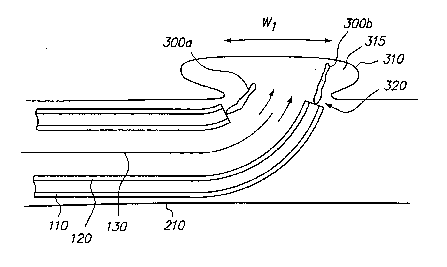
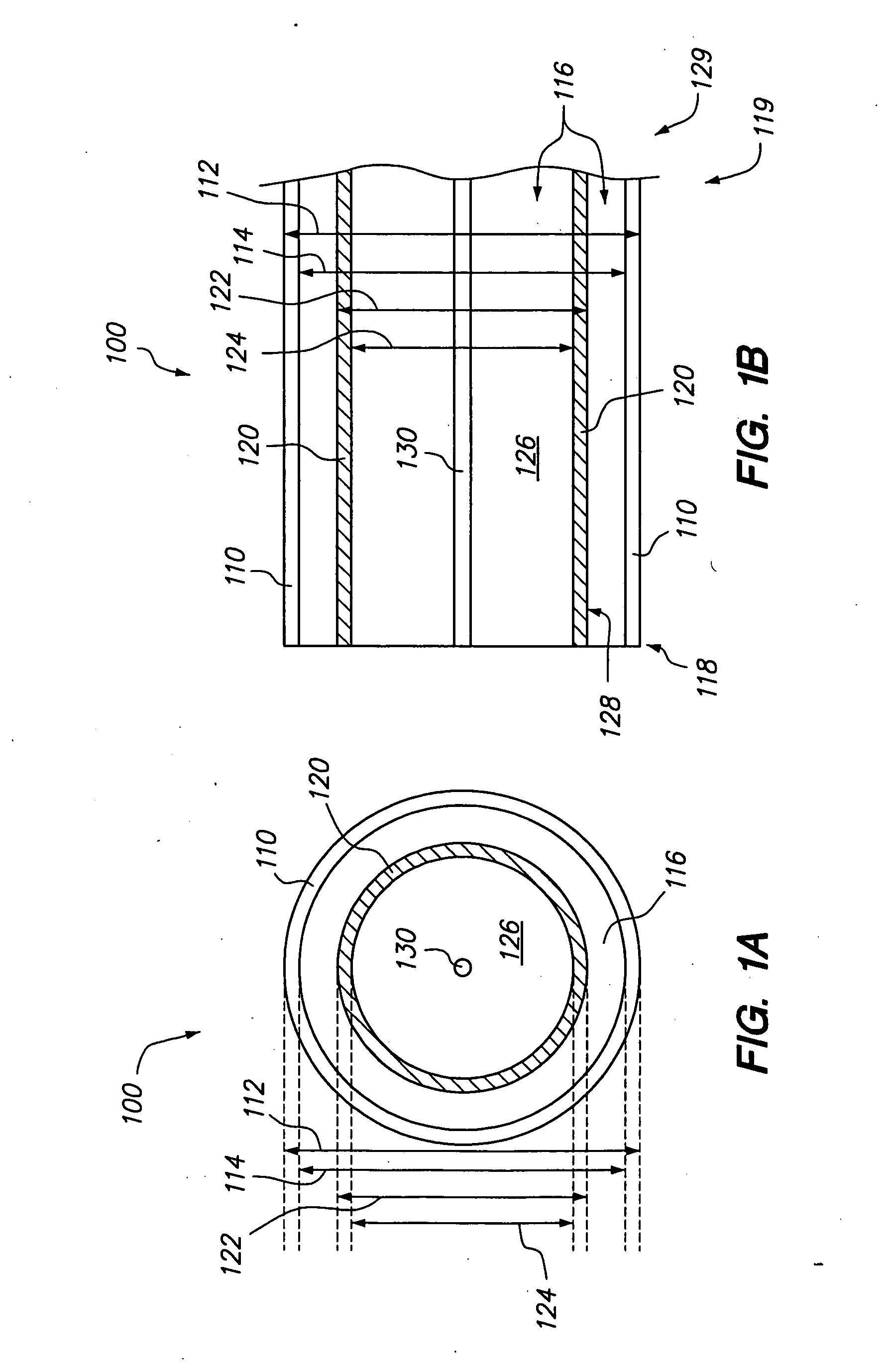
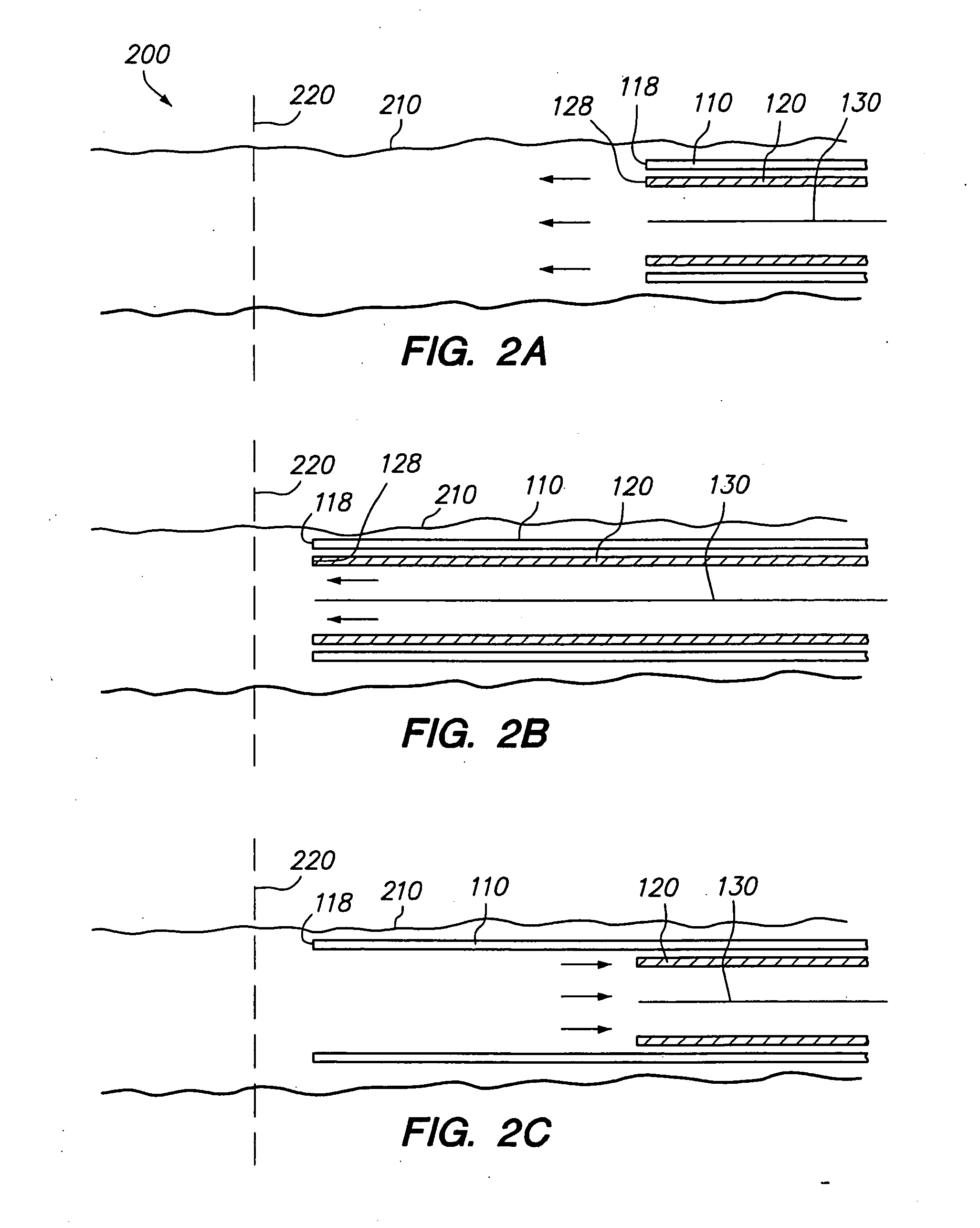
[0018] Referring to FIGS. 1A-B, a system or assembly 100 of the present invention includes a first or delivery member 110, such as an outer, annular catheter or sheath, a second or reducing member 120, such as an inner, annular catheter or sheath, and a guide 130, such as a guide wire. The system 100 is used to deliver an implant (not shown) through a vascular space to a vascular site, such as an aneurysm, tumor, a site for capturing embolic debris, or other vascular malformation (generally vascular site).

[0019] The present invention is suitable for delivering or advancing various devices or implants into the body of a patient for different applications. For example, the present invention can be used to deliver a vaso-occlusive implant, such as a coil and a liquid, to treat or occlude an aneurysm. Further, the present invention can be used to deliver an embolic containment implant which facilitates delivery of a vaso-occlusive implant by, for example, reducing the size of the apert...


PUM


Abstract

A method and system for inserting an implant, such as vaso-occlusive device, an embolic containment device, or a stent into a vascular space to a vascular site in a body utilizing a lumen-reducing catheter. The method and system can be used to treat aneurysm, tumors and other vascular malformations. A guide is inserted into the vascular space. First and second catheters are inserted into the vascular space along the guide. The first or delivery catheter defines a first cavity, and the second or lumen-reducing catheter defines a second, smaller cavity. The second catheter is inserted within the first catheter. In one embodiment, an implant is advanced together with the first and second catheters to a vascular site. In an alternative embodiment, after the first and second catheters are positioned, the guide and the second catheter are removed from the first cavity, and an implant is inserted through the first cavity. With these configurations, radial movement of the guide is restricted to the smaller, second cavity rather than the larger, first cavity.

Description

FIELD OF THE INVENTION [0001] The field of the invention relates to implantable devices, and more particularly, to a method and system for inserting a delivery sheath or catheter through a vascular body using a lumen-reducing catheter and delivering an implantable device through the delivery catheter or the lumen-reducing catheter. BACKGROUND [0002] In many clinical situations, blood vessels are occluded with various implants to control bleeding, prevent blood supply to tumors, block blood flow within an aneurysm or other vascular malformations. Intracranial aneurysms, for example, may rupture causing significant bleeding. The significant bleeding may permanently damage the surrounding brain tissue, possibly causing serious injury and death. Intracranial aneurysms may be particularly difficult to access and treat when they are formed in remote cerebral blood vessels. If left untreated, hemodynamic forces of normal pulsatile blood flow can rupture fragile tissue in the area of the an...

Claims


Application Information

Patent Timeline
Patent Type & Authority Applications(United States)
IPC IPC(8): A61B17/12A61F2/06A61F2/84
CPCA61B17/12022A61B17/12109A61B17/12113A61F2/966A61B2017/12063A61F2/95A61B17/12145
Inventor WALLACE, MICHAEL P.
Owner STRYKER EURO OPERATIONS HLDG LLC
Why Eureka
Try Eureka