Method and human-machine-interface (HMI) system for controlling and monitoring a technical installation

a technology of human-machine interface and technical installation, which is applied in the direction of electric controllers, instruments, ignition automatic control, etc., can solve the problems of limited flexibility of such an hmi device, drawbacks of the technology connected thereto, and limited freedom of movement of the hmi device, so as to improve spatial and data-related flexibility

Active Publication Date: 2005-01-27
SIEMENS AG
View PDF6 Cites 63 Cited by
  • Summary
  • Abstract
  • Description
  • Claims
  • Application Information

AI Technical Summary

Benefits of technology

It is one object of the invention to provide a method for controlling and monitoring a technical installation, and an associated HMI system

Problems solved by technology

However, such a fixed, data-related allocation or assignment of an HMI device to an automation system and the technical installation connected thereto has drawbacks.
Since all the machine and control specific data of the installation is fixedly stored in the HMI device, the flexibility of such an HMI device is usually limited.
Thus, an operator has to go to the location of the respect

Method used


Image

  • Method and human-machine-interface (HMI) system for controlling and monitoring a technical installation
  • Method and human-machine-interface (HMI) system for controlling and monitoring a technical installation
  • Method and human-machine-interface (HMI) system for controlling and monitoring a technical installation

Examples


first embodiment

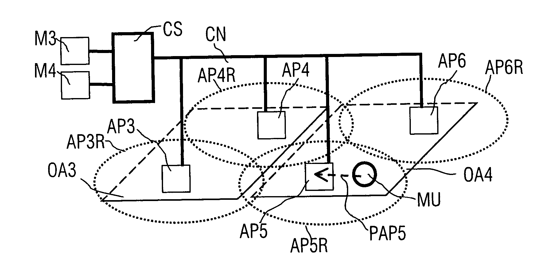
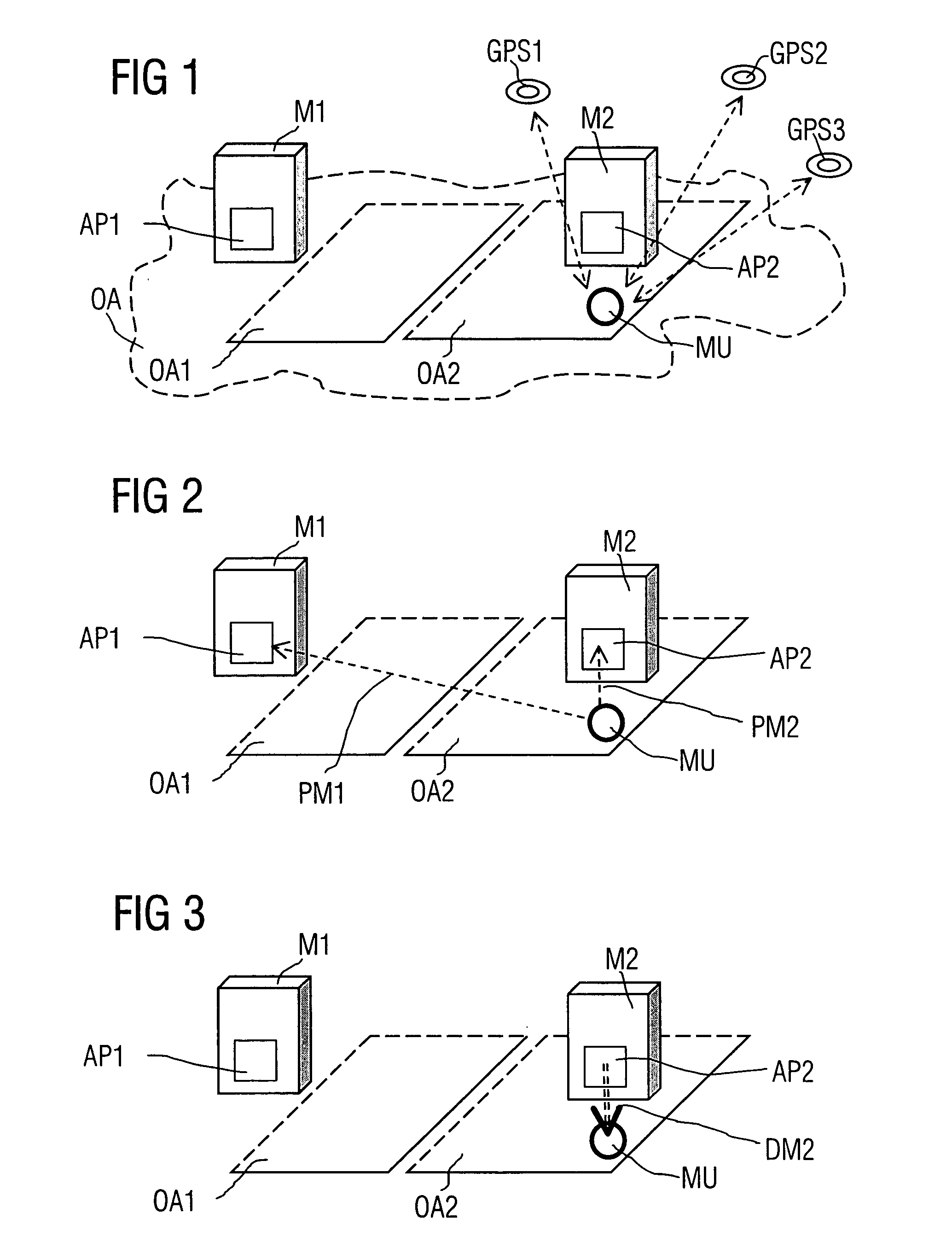
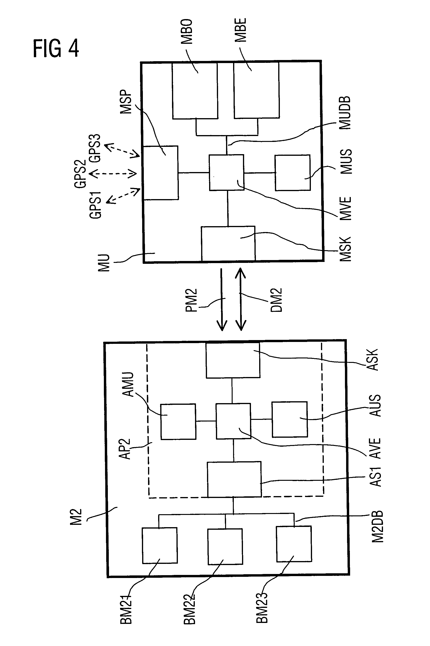
an HMI system according to the invention will now be described with reference to FIG. 1 to 3. The figures show, by way of example, a control area OA, in which a first and a second technical installation M1, M2 are arranged. The two technical installations M1, M2 can be, for example, processing machines or machine tools and can represent a part of an entire plant area, e.g., a large technical installation. According to the invention, an HMI data module AP1, AP2, respectively, is assigned to the technical installations M1, M2. In FIG. 1 to 3, these HMI data modules are integrated into the respective technical installations, but they can also be placed in the immediate spatial surroundings thereof.

The control area OA includes, for example, a first regional control area OA1 and a second regional control area OA2. The first regional control area OA1 is assigned, for example, to the technical installation M1 located adjacent thereto and is managed by the first HMI data module AP1, which ...


PUM


Abstract

A method and associated system for controlling and monitoring a technical installation (M1, M2), which is assigned at least one regional control area (OA1, OA2), uses a universal, mobile control and monitoring module (MU) and includes three steps. In a first step, the current position of the mobile control and monitoring module (MU) is determined by means of positioning signals. In a second step, the mobile control and monitoring module (MU) is assigned to a technical installation (M1, M2), if the current position of the mobile control and monitoring module lies within the regional control area (OA1, OA2) of that technical installation (M1, M2). In a third step, HMI data of the technical installation (M1, M2) is loaded into the assigned mobile control and monitoring module (MU). The assignment of the universal, mobile control and monitoring module (MU) to the technical installation (M1, M2) is not fixed or permanent, but only temporary. Thus, only HMI data that are required to carry out the respectively desired control and monitoring tasks on the assigned technical installation (M1, M2), or on a certain part thereof, needs to be selectively loaded into the control and monitoring module (MU). If an operator carries along the control and monitoring module (MU), he or she can leave the regional control area (OA1, OA2) of the technical installation (M1, M2) and enter the regional control area (OA1, OA2) of another technical installation (M1, M2) without restrictions. Then, a temporary assignment to that installation is possible.

Description

The following disclosure is based on European Patent Application No. 03016487.5, filed on Jul. 22, 2003, which is incorporated into this application by reference. FIELD OF AND BACKGROUND OF THE INVENTION The invention relates to a method and an HMI system for controlling and monitoring a technical installation. Technical installations include all types of technical equipment and systems, both individually in stand-alone arrangements and interconnected in data networks, e.g., via a field bus. In industrial applications, such technical installations include individual apparatuses, such as drives and processing machines. However, a technical installation can also be a production plant, in which an entire technical process is operated by locally distributed control apparatuses. Such a production facility is, for example, a chemical facility or an assembly line. Technical installations are controlled and operated by special digital data processing systems, which are also referred to a...

Claims


Application Information

Patent Timeline
IPC IPC(8): G08C19/28
CPCG08C19/28
Inventor DE MEYER, FREDERIKHEYMANN, ROLAND
Owner SIEMENS AG
Why Eureka
Try Eureka