
Method for reducing the measurement requirements for the dynamic response of tools in a CNC machine

a technology of dynamic response and measurement requirements, applied in the field of cnc (computer numerical control) programming and machining, can solve the problems of lack of repeatability, difficult manual measurement, and inability to meet the needs of specialized equipment and analysis,

Inactive Publication Date: 2005-01-27
ESTERLING DONALD M
View PDF1 Cites 34 Cited by
  • Summary
  • Abstract
  • Description
  • Claims
  • Application Information

AI Technical Summary

Benefits of technology

Recently, Esterling has developed a simpler, non-contact device for measuring the FRF of a tool situated in a CNC machine. Combining this device with the present invention will greatly simplify the overall dynamic measurement process.
The measurements of the FRFs X1 / F1 through X2 / F2 do not require any new procedure. The FRFs may be obtained with the standard calibrated hammer impact measurement technique or with the Esterling non-contact technique. This is an advantage of the method since the measurement technique is already well established. Conventional FRF measurement requires the X / F measurement for every tool in the tool carrel. Our inverse RCSA method takes a single tool and makes four X / F measurements. (One of the measurements is redundant and can serve as a consistency check on the measurement process). These measurements are used to determine tooling-independent receptances of the CNC machine / spindle / tool holder complex (“b1, b2, b3”) which can then be used with standard (forward) RCSA (e.g. Equations [7] and [8]) to obtain the receptances of tools which share a common or similar CNC machine, spindle and tool holder type. The result is substantial reduction in required FRF measurements.
The method entails measuring the FRFs under four conditions ([M1], [M2], [M3] and [M4]) for a particular tool (T1) and then using inverse RCSA followed by standard (forward) RCSA to obtain the FRF for any tool situated in the same or similar tool holder, spindle and CNC machine. In principal, the method works for any tool (T1) as the tool used for the measurements. In practice, the standard tool (T1) should be a cylindrical rod with simple geometry. The simple geometry leads to relatively simple and reliable free-free receptances (a1 . . . , A1, . . . ) for the standard tool, as used in equations [13]-[23]. The top portion of the rod (e.g. the top one inch) may be considered as part of the B “top subsystem”) as it is not usually practical to apply a force or take displacement measurements exactly at the tool—tool holder interface, due to interference from the tool holder overhang. This is not a problem for the method, as the “A” subsystem is then taken as the portion of the tool below this upper section of the rod.
This will introduce a small variation of the “B” sub-system receptance for tools with densities and / or diameters that differ from the standard tool, due to the mass of the tool in the tool holder itself as well as the section just below the tool holder and now considered as part of the “B” subsystem. This mass effect is easily incorporated into the method, since the effect of a point mass (a reasonable approximation for the effect of the short tool section on the very massive tool holder / spindle) on FRFs is well known and documented, for example, in Bishop and Johnson. So the “mass effect” of any tool can be subtracted out of the FRF relationships for tool T1 and incorporated into subsequent FRF evaluations for tools with different densities or diameters.
The advantage of our inverse RCSA method is that we can obtain the needed “B subsystem” FRFs with no special assumptions and using only linear relationships, removing the uncertainties and imprecision of a numerical solution of non-linear equations. Further, the needed measurements are standard displacement over force FRF measurements, albeit with the forces and displacements set at unique locations. The only uncertainties are the inherent imprecision of any measurement.

Problems solved by technology

These manual measurements can be difficult to perform, lack repeatability, require specialized equipment and analysis and so require a trained expert.
Consequently, their method results in certain phenomenological parameters related to the tool holder dynamics that vary as the tool geometry is changed.

Method used


Image

  • Method for reducing the measurement requirements for the dynamic response of tools in a CNC machine
  • Method for reducing the measurement requirements for the dynamic response of tools in a CNC machine
  • Method for reducing the measurement requirements for the dynamic response of tools in a CNC machine

Examples


example

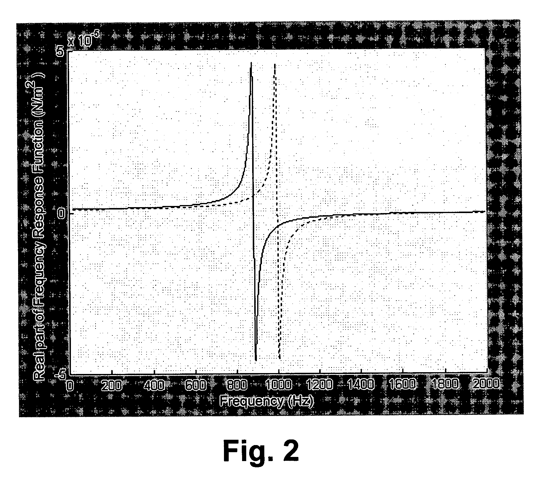
The method will be demonstrated using an example compound system with computer-generated data. A cylindrical beam with a cantilever end condition will be used to generate the FRF (or receptance) for a sample system. The beam will be considered as composed of two sections. The top (“B”) section will be attached to a fixed boundary (cantilever end condition). The lower (“A”) section will be attached to the upper B section. The B section represents the CNC machine, spindle, tool holder and a short section of the tool. The A section represents a tool extending beyond the short tool section.

For simplicity, the tooling in both sections will have the same diameter (D). The lower section will have length La and the upper section will have length Lb. Both sections will have a diameter of 0.5 inches with material properties representative of 1018 steel. The modulus E for each section will be 30.04*106 psi. The density is 0.284 lb per cubic inch. In order to model damping, we will consider ...


PUM


Abstract

The present invention provides a method for determining the Frequency Response Function for a collection of tools in a CNC machine by taking four measurements (three of which are independent) on a single tool, held in the same or similar tool holder, spindle and CNC machine. The method uses inverse Receptance Coupling Substructure Analysis (RCSA) to obtain the receptances of the system, exclusive of the single tool. Standard (forward) RCSA is then used with these receptances and certain analytic expressions for the receptances of a freely supported tool to obtain the FRF for each tool in the collection of tools. This information can be used to predict stable, chatter-free depths of cut over a range of spindle speeds in CNC machining, identifying both the limiting depth of cut at any speed as well as special spindle speeds where unusually large, chatter-free depths of cut are available.

Description

BACKGROUND OF THE INVENTION Common Abbreviations and Terms The following are abbreviations and terms that will be used in portions of this application. For convenience, the abbreviations and terms are collected here for reference. Details on the particular meaning of each term may be found at the first use of the term. CNC Computer Numerical Control Type of machine tool whose operation is controlled by a computer. May also refer to the control itself or to the programming language used by the control. FRF Frequency Response Function Linear relation between an applied force and the resulting system displacement, expressed in the frequency domain. “Receptance” and Frequency Response Function may be used interchangeably. A particular term is used depending on the context and conventional usage for that context. RCSA Receptance Coupling Substructure Analysis Method for obtaining the Frequency Response Function for a compound system from the Frequency Response Functions of the com...

Claims


Application Information

Patent Timeline
IPC IPC(8): G05B19/401G06F19/00
CPCG05B19/401
Inventor ESTERLING, DONALD M.
Owner ESTERLING DONALD M
Learn More