Method and apparatus for moving image conversion, method and apparatus for moving image transmission, and programs therefor

Active Publication Date: 2005-01-27
META PLATFORMS INC
View PDF26 Cites 30 Cited by
  • Summary
  • Abstract
  • Description
  • Claims
  • Application Information

AI Technical Summary

Benefits of technology

[0015] The present invention has been conceived based on consideration of the above circumstances. An object of the present invention is therefore to enable high-quality image display wherein frames are con

Problems solved by technology

However, there are some models of mobile terminals that cannot display a moving image.
Meanwhile, regardless of an increase in the number of pixels in a display screen, capacity of a memory installed in a mobile terminal for image display is not large due to high cost or the like.
Therefore, although a compression ratio can be improved in the case where pixels having the same value are align

Method used


Image

  • Method and apparatus for moving image conversion, method and apparatus for moving image transmission, and programs therefor
  • Method and apparatus for moving image conversion, method and apparatus for moving image transmission, and programs therefor
  • Method and apparatus for moving image conversion, method and apparatus for moving image transmission, and programs therefor

Examples


first embodiment

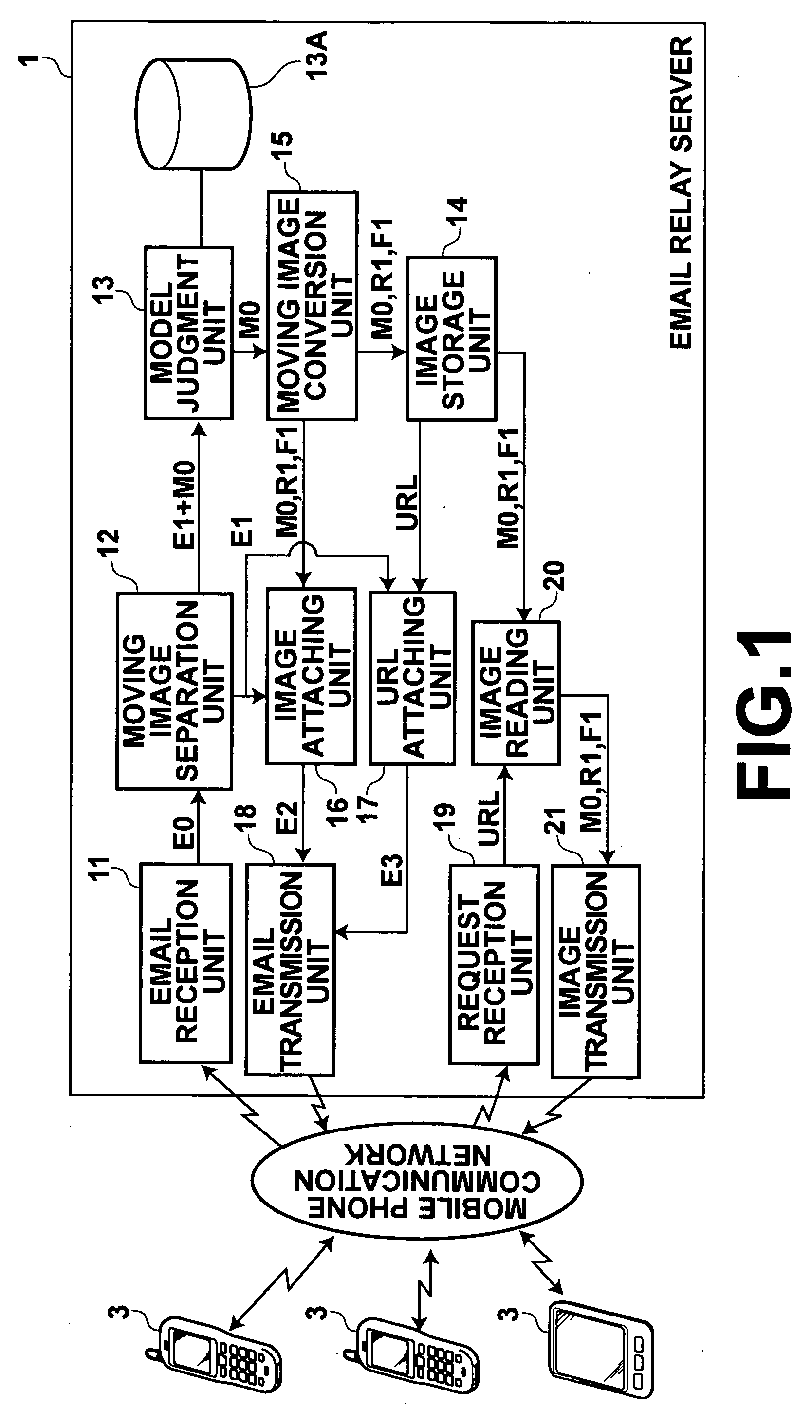
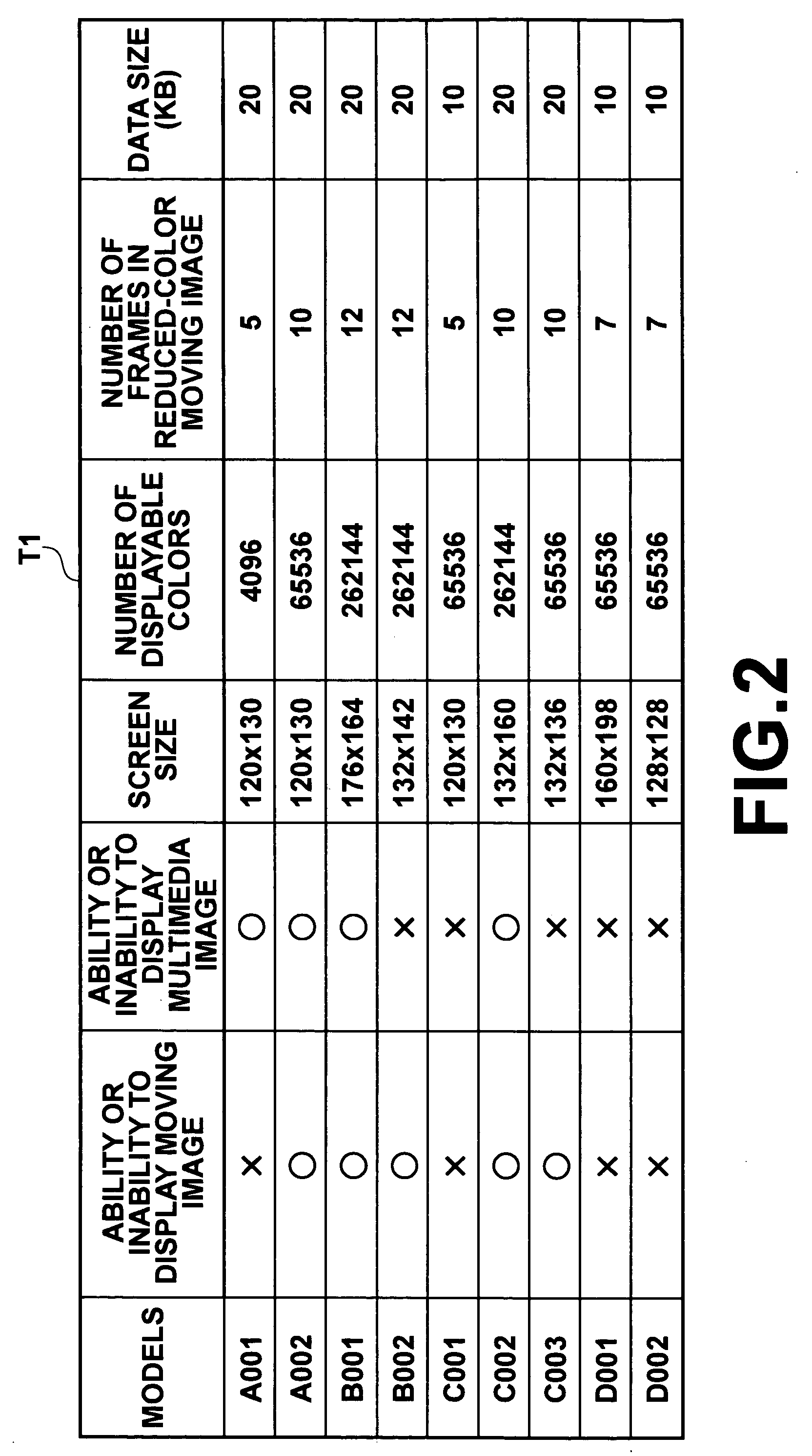
[0132] A procedure carried out in the first embodiment will be explained next. FIG. 6 is a flow chart showing the procedure. When the email reception unit 11 receives the email E0 attached with the moving image data set M0 from the sender terminal 3, the procedure starts. The moving image separation unit 12 separates the moving image data set M0 from the email E0 (Step S1). The model judgment unit 13 judges which of the cases (1) to (4) is the case for the destination terminal 3, by referring to the database 13A based on the destination email address included in the header of the main content E1 (Step S2).

[0133] If the result is the case (1), the procedure goes to a flow chart shown in FIG. 7. The model judgment unit 13 and the moving image separation unit 12 respectively input the moving image data set M0 and the main content E1 to the image attaching unit 16 (Step S3). The image attaching unit 16 generates the image-attached email E2 by attaching the moving image data set M0 to th...

second embodiment

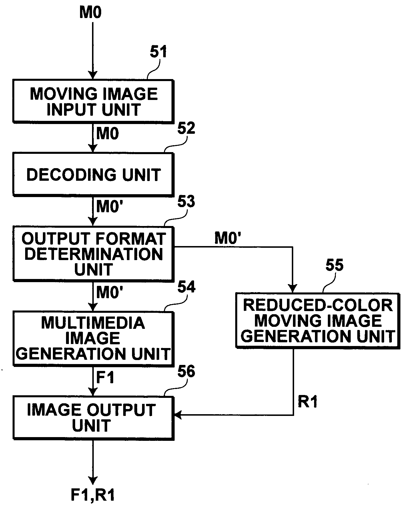
[0177] As has been described above, in the second embodiment, the model of the terminal 3 as the destination of an email E0 attached with the moving image data set M0 is judged first. The moving image data set M0 attached to the email E0 is converted into the reduced-color moving image data set R1 and sent to the destination terminal 3 in the case where the model is not capable of moving image display. Therefore, even if the destination terminal 3 cannot carry out moving image display, pseudo moving image display can be realized based on the reduced-color moving image data set R1.

[0178] When the reduced-color moving image data set R1 is generated from the moving image data set M0, only the palette data set P0 is generated. Therefore, unlike the method described in Japanese Unexamined Patent Publication No. 11(1999)-259640, generation of palette data sets for every several frames becomes unnecessary. As a result, the reduced-color moving image data set R1 can be obtained from the mov...


PUM


Abstract

Even if an email attached with a moving image is sent to a terminal that is not capable of moving image display, pseudo moving image display can be carried out in high quality on the terminal. An email reception unit receives the email, and a model judgment unit judges the model of the terminal as a destination of the email. If the destination terminal cannot display the moving image, a moving image conversion unit generates a multimedia image data in a multimedia format from moving image data representing the moving image. An image attaching unit attaches the moving mage data or the multimedia image data to main content of the email, and an email transmission unit sends the image-attached email to the destination terminal.

Description

BACKGROUND OF THE INVENTION [0001] 1. Field of the Invention [0002] The present invention relates to an email relay apparatus and an email relay method for relaying an email attached with a moving image to a destination. The present invention also relates to a program causing a computer to execute the email relay method. [0003] 2. Description of the Related Art [0004] An image obtained by a digital camera, a scanner, or the like can represent 24-bit colors (that is, approximately 16.77 million colors) wherein 8 bits each are assigned to R, G, and B. However, some reproduction apparatus are capable of reproducing fewer colors such as 256 colors. Furthermore, an image format used frequently in Web sites (such as GIF or PNG) can deal with only 256 colors. Therefore, for displaying an image obtained by a digital camera or the like on a reproduction apparatus which can display fewer colors, or for converting the image into an image format such as GIF or PNG, the 16.77 million colors need...

Claims


Application Information

Patent Timeline
IPC IPC(8): H04L12/58H04Q7/34
CPCH04L12/5835H04L51/066H04L12/5895H04L51/58G06F16/116
Inventor NONAKA, SHUNICHIRO
Owner META PLATFORMS INC
Why Eureka
Try Eureka