
Mass memory device based on a flash memory with multiple buffers

a mass memory device and buffer technology, applied in the field of mass memory devices, can solve the problems of mass memory devices completely unusable for a relatively long period, data blocks cannot be updated any longer, and the defragmentation procedure is rather inefficien

Inactive Publication Date: 2005-01-27
STMICROELECTRONICS SRL
View PDF7 Cites 59 Cited by
  • Summary
  • Abstract
  • Description
  • Claims
  • Application Information

AI Technical Summary

Benefits of technology

[0017]FIGS. 4a-4b represent the operation of t...

Problems solved by technology

Therefore, once a block of data has been written into the flash memory, this block of data cannot be updated any longer (unless the respective whole sector is erased).
Nevertheless, the defrag procedure is rather inefficient (especially when the flash memory has a NOR architecture, wherein the erasing is extremely slow).
Particularly, this procedure makes the mass memory device completely unusable for a relatively long period (up to 2s).
Therefore, the busy period can easily exceed a maximum allowable time-out; in this condition, the mass memory device is seen as being blocked by the processing system in which it is inserted.
Nevertheless, once the buffer is full as well, the same problems described above are experienced.

Method used


Image

  • Mass memory device based on a flash memory with multiple buffers
  • Mass memory device based on a flash memory with multiple buffers
  • Mass memory device based on a flash memory with multiple buffers

Examples


Embodiment Construction

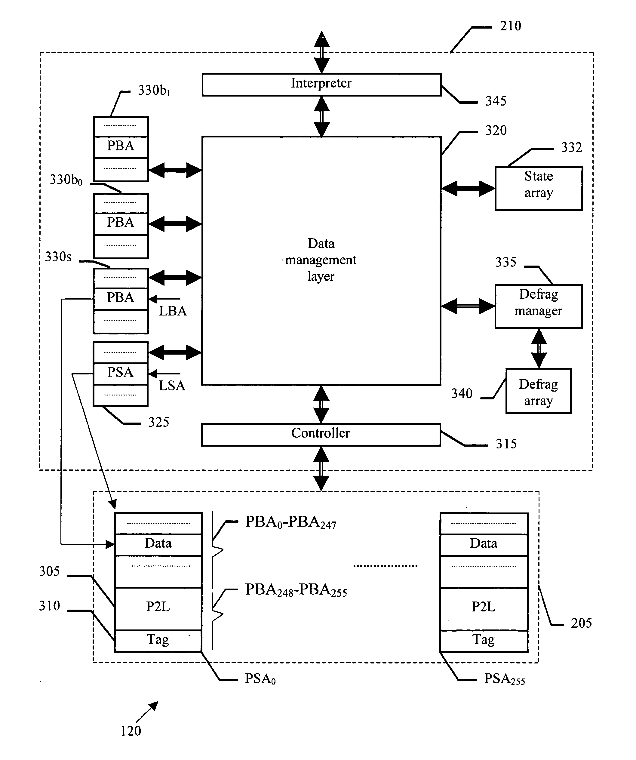
[0019] It should be understood that these embodiments are only examples of the many advantageous uses of the innovative teachings herein. In general, statements made in the specification of the present application do not necessarily limit any of the various claimed inventions. Moreover, some statements may apply to some inventive features but not to others. In general, unless otherwise indicated, singular elements may be in the plural and vice versa with no loss of generality.

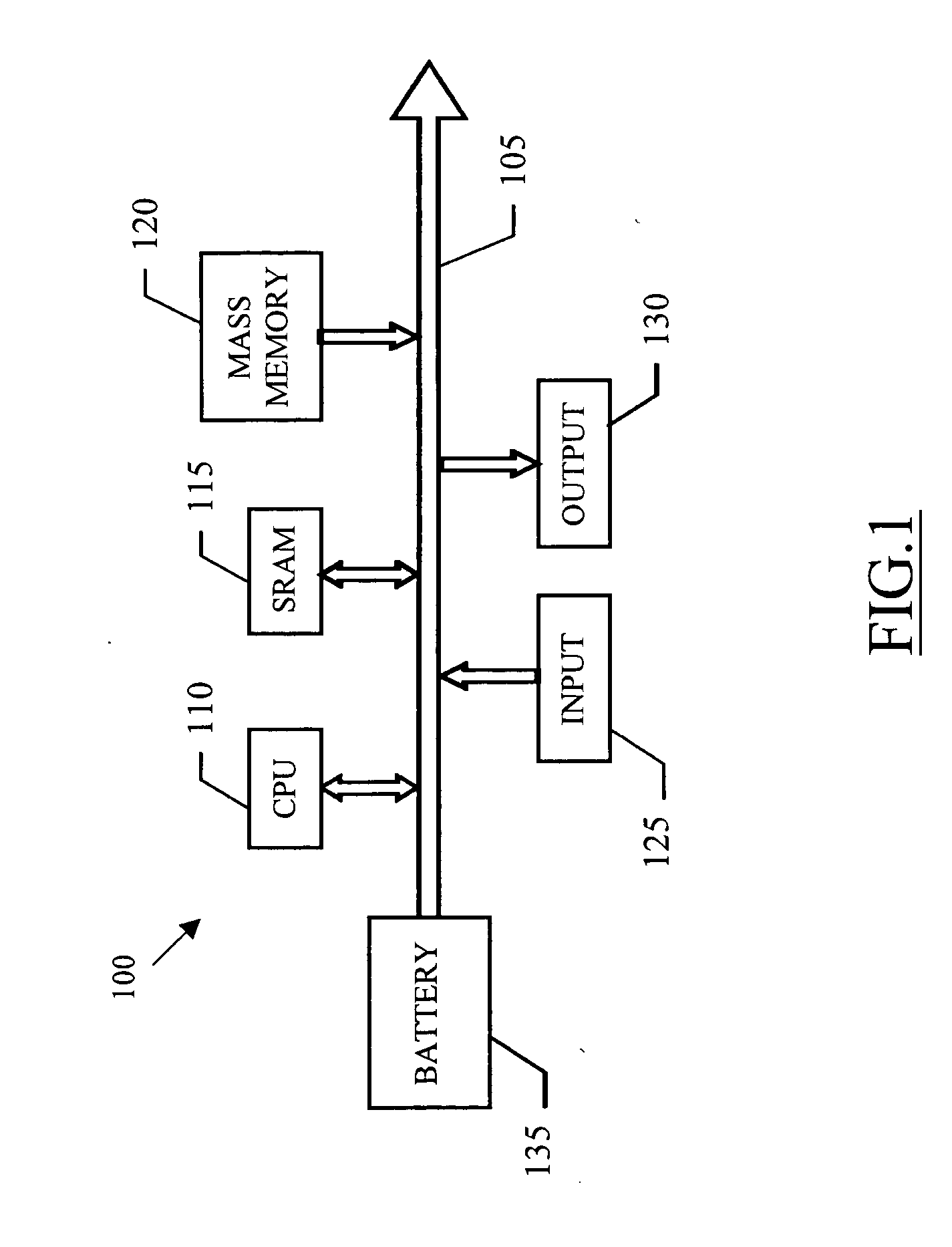
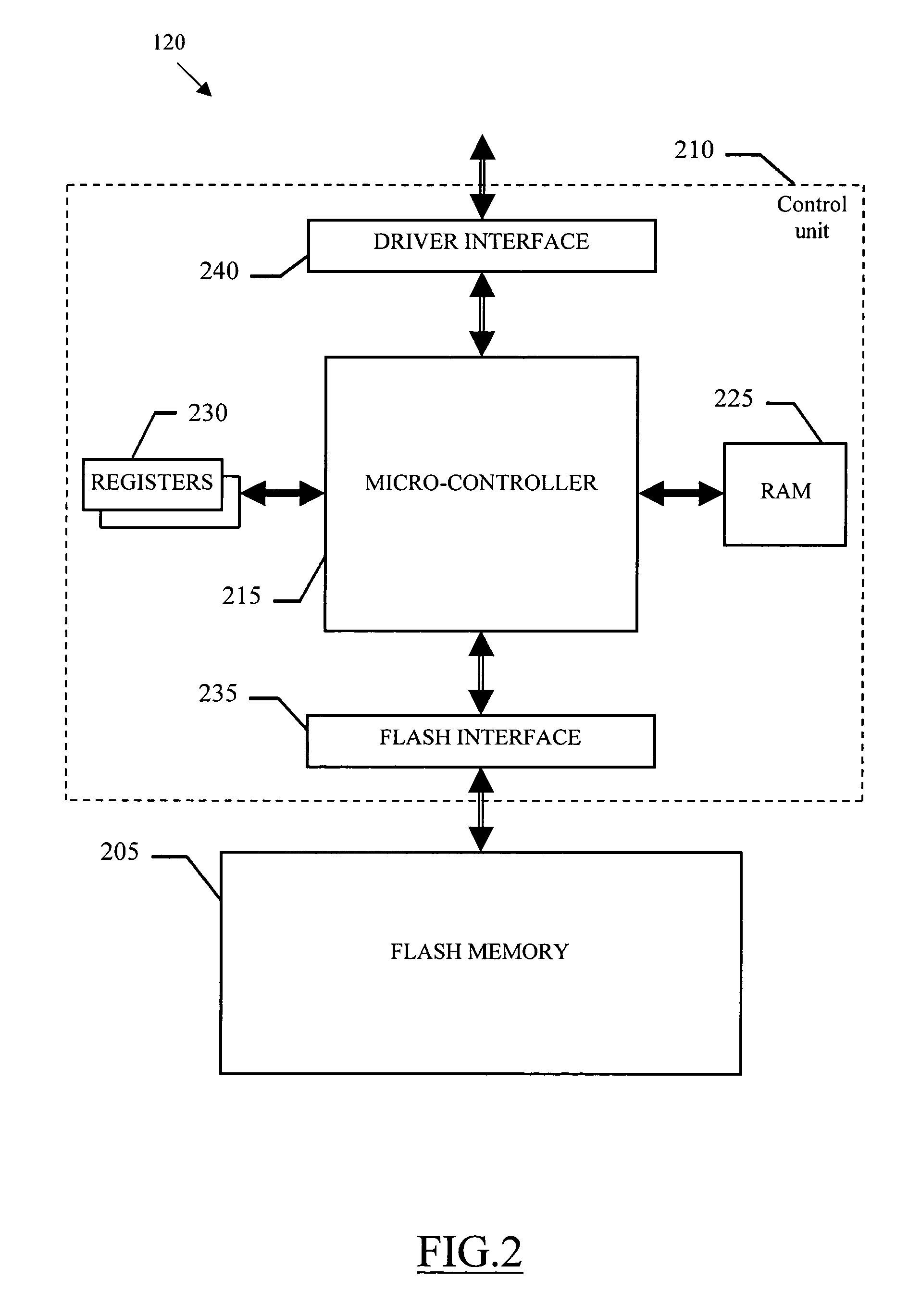
[0020] With reference in particular to FIG. 1, a palmtop computer 100 is illustrated in schematic form. The computer 100 is formed by several units, which are connected in parallel to a communication bus 105. In detail, a Central Processing Unit (CPU) 110 controls operation of the computer 100. The CPU 110 is connected to a working memory (SRAM) 115 in a conventional manner. Several peripheral units are further connected to the bus 105 (through respective drives). Particularly, the computer 100 is provided wit...


PUM


Abstract

The mass memory device includes a flash memory (205) having a plurality of physical sectors, suitable to be erased individually, each one including a plurality of physical blocks and a method for emulating a random-access logical memory space having a plurality of logical sectors each one including a plurality of logical blocks, the logical sectors being grouped into at least one group. The method includes partitioning a random-access logical memory space into a plurality of logical sectors each one including a plurality of logical blocks, the logical sectors being grouped into at least one group of logical sectors; associating a corresponding data physical sector with each of the logical sectors and associating a plurality of corresponding buffer physical sectors with each group of logical sectors; setting at least one of the buffer physical sectors as an active buffer physical sector; writing each of the logical blocks into one of an available physical block of the corresponding data physical sector if the corresponding data physical sector is not full; and the corresponding active buffer physical sector if the corresponding data physical sector is full; setting another buffer physical sector as active, in response to the active buffer physical sector becoming full; and defragging each data physical sector which is full and associated with a logical sector having at least one logical block stored in the corresponding buffer physical sector which is full.

Description

CROSS-REFERENCE TO RELATED APPLICATIONS [0001] This application is based upon and claims priority from prior Italian Application No. MI2003A001126, filed on Jun. 5, 2003 the entire disclosure of which is herein incorporated by reference. FIELD OF THE INVENTION [0002] The present invention generally relates to a mass memory device and more particularly to a non-volatile mass memory device such as flash memory. BACKGROUND OF THE INVENTION [0003] Mass memory devices (such as magnetic hard-disks) are commonly used in a processing system for storing data that must be preserved even when the power supply is off. A new technology for the mass memory devices (based on flash memories) has become particularly competitive in the last years. These mass memory devices are compact, robust and with low consumption; therefore, they result very advantageous especially in portable processing systems. [0004] As it is known, a flash memory can be erased only in sectors having relatively large sizes (fo...

Claims


Application Information

Patent Timeline
IPC IPC(8): G06F12/02G06F12/08
CPCG06F12/0246G06F2212/7205G06F2212/7203
Inventor IACULO, MASSIMOGUIDA, NICOLAPOLLIO, ANTONINODELLAMONICA, ANGELOBAGGI, PIETROGHEZZI, STEFANO
Owner STMICROELECTRONICS SRL
Learn More