Method of making a metallic thin wire and a medical tool into which the metallic thin wire is incorporated

Inactive Publication Date: 2005-02-03
ASAHI INTECC CO LTD
View PDF8 Cites 11 Cited by
  • Summary
  • Abstract
  • Description
  • Claims
  • Application Information

AI Technical Summary

Benefits of technology

[0012] According to the present invention, there is provided a method of making a metallic thin wire which is twisted in one direction under a tensile weight applied in the lengthwise direction, or primarily and secondarily twisted alternately in one direction and the opposite direction under the tensile weight applied in the lengthwise direction. This induces a uniform torsional rigidity in the right and left directions through an entire length of the one single metallic thin wire.
[0013] According to other aspect of the present invention, one single metallic thin wire is prepared to have a predetermined length or a bifold extension of the predetermined length. A middle portion of the one single metallic thin wire is fixedly supported at a fixed portion. Front and rear half portions of the one single metallic thin wire is twisted (in one direction) with the front and rear half portions symmetrically located at both sides of the fixed portion. At the time of twising the front and rear half portions, a tensile weight is concurrently applied to the front and rear half portions. This produces two metallic thin wires simultaneously in a dual-way fashion to maintain the product quality uniform while improving the productivity.

Problems solved by technology

It is, however, poor in torsional characteristics.
This leads to a shortage of the torque transmissibility and rotational maneuverability so as to reduce the steerability.
This makes the catheter guide wire costly and disadvantageous especially when brought to the mass production.
In addition, the metallic thin wire is twisted only in one direction, and thus making the torsional characteristics uneven in the lengthwise direction.

Method used


Image

  • Method of making a metallic thin wire and a medical tool into which the metallic thin wire is incorporated
  • Method of making a metallic thin wire and a medical tool into which the metallic thin wire is incorporated
  • Method of making a metallic thin wire and a medical tool into which the metallic thin wire is incorporated

Examples


first embodiment

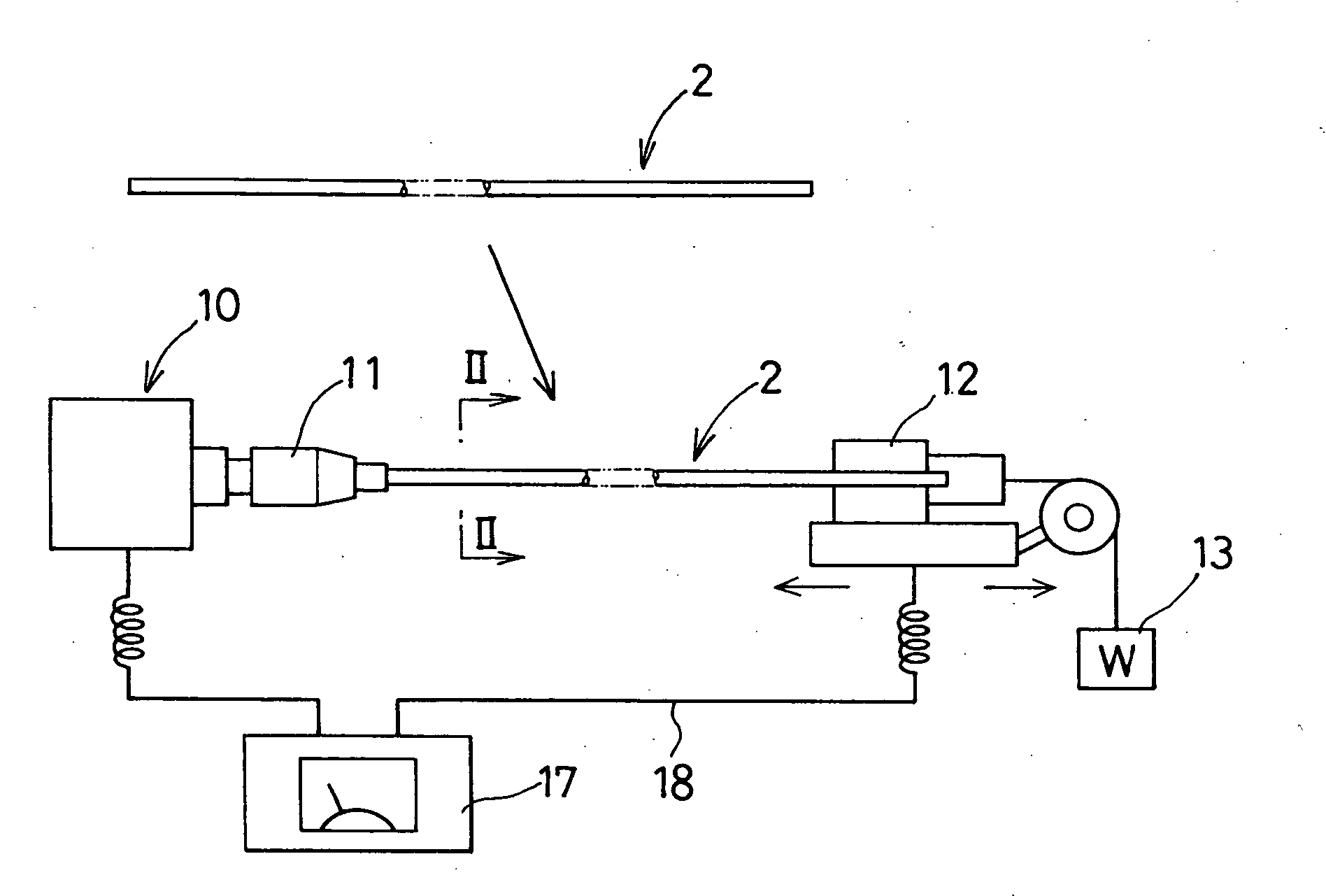
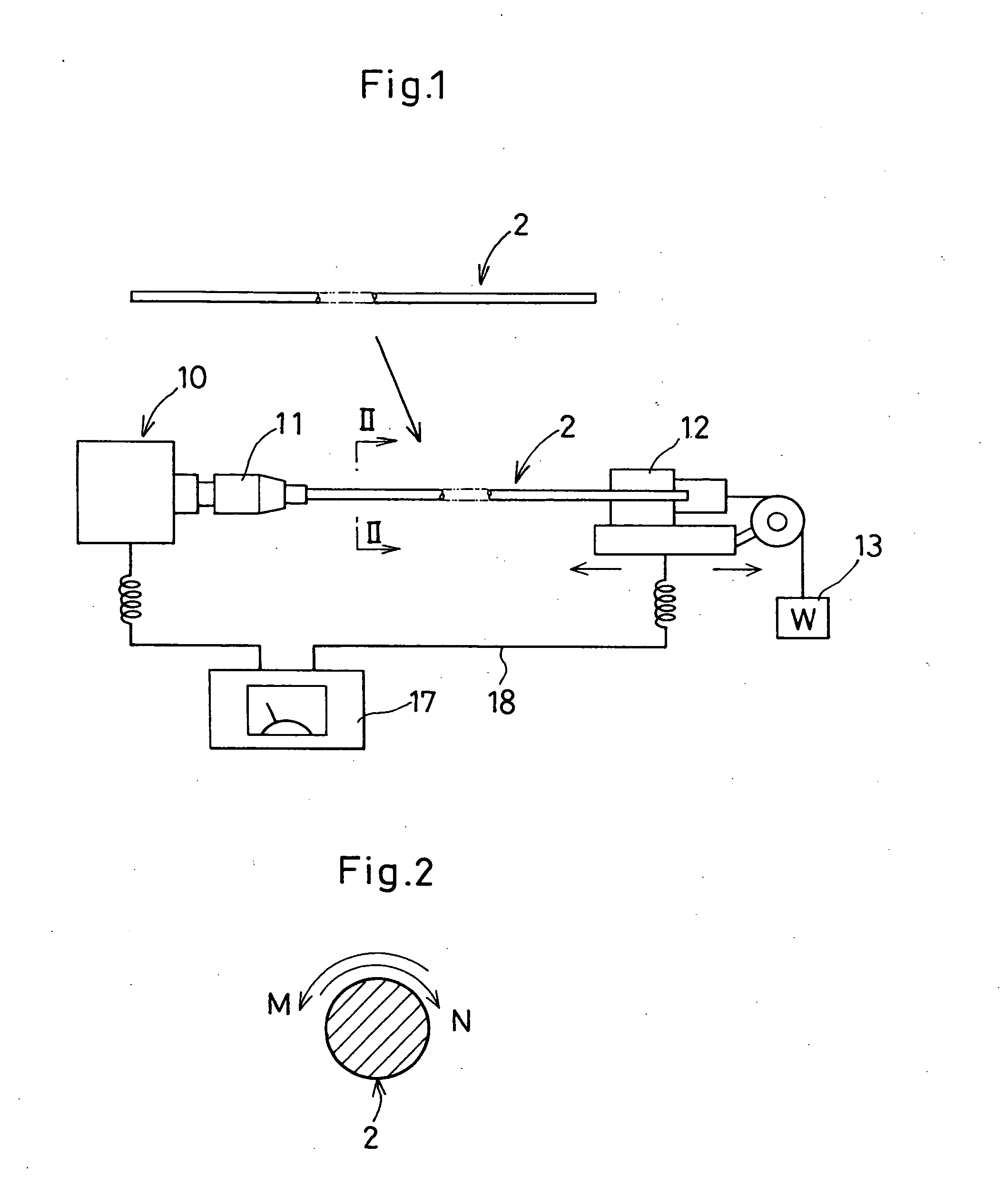
[0042] In the following description of the depicted embodiments, the same reference numerals are used for features of the same type. Referring to FIGS. 1 through 4, a method of making a metallic thin wire 1 according to the invention is described. The metallic thin wire 1 is used to a main wire component of a medicl guide wire 20, 20A and a balloon catheter 21 as shown in FIGS. 13 through 15. As a raw material of the metallic thin wire 1, one single metallic thin wire 2 (referred merely to as “thin wire 2” hereinafter) is drawn and severed to have a predetermined length and diameter as shown in FIG. 1. By way of illustration, the thin wire 2 is made of an austenitic stainless steel, and attached to a twisting device 10 to be twisted and processed with a heat treatment to remove a residual stress as described hereinafter.

[0043] The thin wire 2 has a predetermined length (e.g., 1,000-1,500 mm), one end of which is firmly clamped by a rotary chuck 11. The other end of the thin wire 2 i...

second embodiment

[0050]FIGS. 5 through 8 show the invention in which the thin wire 2 is divided into a plurality of zones X, Y and Z in the lengthwise direction. The zones X, Y and Z in turn have different twisted numbers of times after the thin wire 2 is primarily and secondarily twisted depending on the zones X, Y and Z. When the thin wire 2 is used to the medical guide wire 20, 20A and the balloon catheter 21 as shown in FIGS. 13 through 15, the zone X has the largest numbers of twisted times to position near a hand access section 27 with the smallest numbers of twisted times given to the zone Z. The zone Y, which positions between the zone X and the zone Z, has a middle numbers of twisted times between the largest and smallest numbers of twisted times. In this way, the thin wire 2 are wrought out to have the different numbers of twisted times discretely depending on the zones X, Y and Z.

[0051] In the second embodiment of the invention, an intermediary clamp device 14 is slidably placed between t...

fourth embodiment

[0055]FIG. 12 shows the invention in which a dual rotary chuck 11A is provided in the twisting device 10. An extension of the thin wire 2 is a bifold of the predetermined length. A middle section of the thin wire 2 is firmly clamped by the dual rotary chuck 11A. Both ends of the thin wire 2 is clamped by a slidable chuck 12A which hangs down the tensile weight W.

[0056] In this instance, the thin wire 2 symmetrically locates its right (front) half portion and left (rear) half portion in a dual fashion. Thereafter, the right and left half portions are primarily and secondarily twisted in the same manner as done in the first embodiment of the invention. With the use of the dual rotary chuck 11A, two metallic thin wires can be produced concurrently, thus reducing the manufacturing cost with a high productivity. The two metallic thin wires is produced under the same conditions, thus contributing to equalizing the quality of the product.

[0057]FIG. 13 shows a fifth embodiment of the inven...


PUM

PropertyMeasurementUnit
Weightaaaaaaaaaa
Lengthaaaaaaaaaa
Metallic bondaaaaaaaaaa

Abstract

In a method of making a metallic thin wire (1), one single metallic thin wire (2) is prepared to have a predetermined length with a middle portion of the one single metallic thin wire (2) as a fixed portion. Front and rear half portions of the one single metallic thin wire (2) are twisted with the front and rear portions being symmetrically located at both sides of the fixed portion, while at the same time, applying a tensile weight (W) to the front and rear half portions in the lengthwise direction. The one single metallic thin wire (2) is processed with a heat treatment to remove a residual stress from the one single metallic thin wire (2). Otherwise, the front and rear portions of the one single metallic thin wire (2) is primarily and secondarily twisted alternately under the tensile weight (W) applied in the lengthwise direction. This provides the metallic thin wire (1) with a high rotation-following capability and high torque transmissibility, thus enabling artisans to usefully apply the metallic thin wire (1) to a main wire component (25) of a medical tool and equipment.

Description

BACKGROUND OF THE INVENTION [0001] 1. Field of the Invention [0002] The invention relates to a method of making a metallic thin wire in the form of a flexible wire configuration used as a main wire component of a medical tool such as a catheter, a catheter guide wire, an endscope treating instrument or the like, and particularly concerns to a medical tool produced by the method of making the metallic thin wire. [0003] 2. Description of Prior Art [0004] In a catheter and a catheter guide wire which introduces a leading distal end into a diseased area through a sinuous vascular system, the leading distal end of the catheter or the catheter guide wire is inserted into the blood vessel or the somatic cavity by a “push-pull and turn” manipulation at a hand access portion located outside a subject patient upon treating the diseased area. In an endscope treating instrument which is inserted through a somatic cavity to reach the diseased area, a leading end of the endscope treating instrume...

Claims


Application Information

Patent Timeline
IPC IPC(8): A61M25/01A61M25/09A61M25/16B21C37/04B21F7/00B21F99/00C21D1/30C21D7/10C21D8/06C21D9/52
CPCA61M25/0133A61M25/09A61M2025/09108A61M2025/09191B21C37/045Y10T29/5121B21F99/00C21D1/30C21D7/10C21D8/065Y10T29/5187B21F7/00
Inventor KATO, TOMIHISAMIYATA, KENJI
Owner ASAHI INTECC CO LTD
Why Eureka
Try Eureka