
System and method to detect and correct spark plug fouling in a marine engine

a marine engine and spark plug technology, applied in the direction of machines/engines, automatic control of ignition, electric control, etc., can solve the problems of direct ignition of unvaporized fuel, soot production in the combustion chamber, and soot formation in the combustion chamber, and achieve the effect of low ionization

Active Publication Date: 2005-02-03
BRP US
View PDF5 Cites 22 Cited by
  • Summary
  • Abstract
  • Description
  • Claims
  • Application Information

AI Technical Summary

Benefits of technology

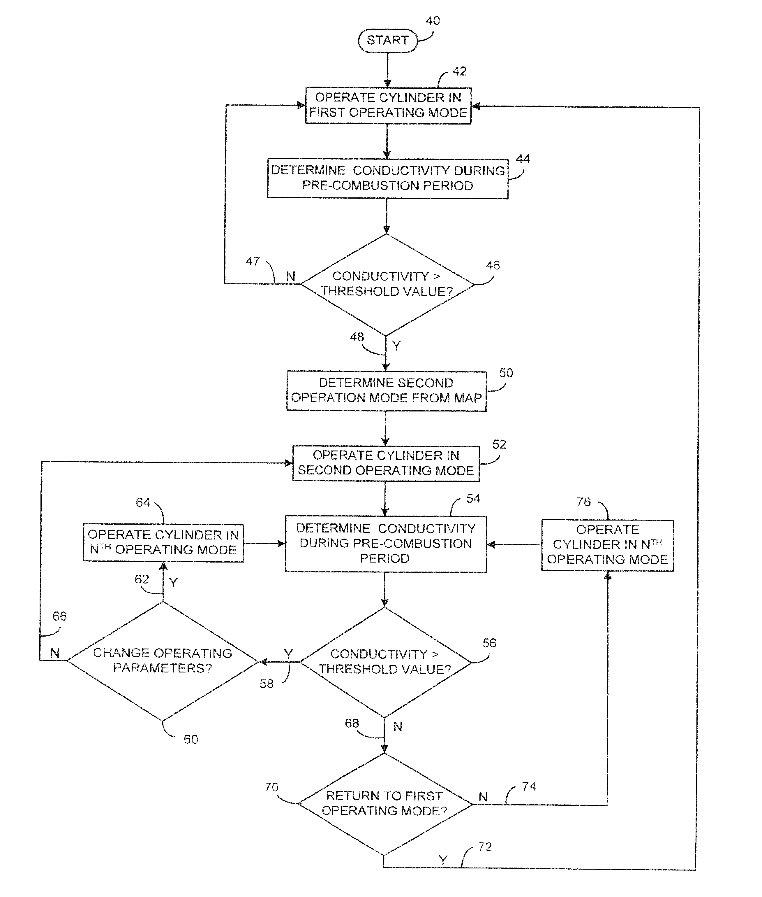
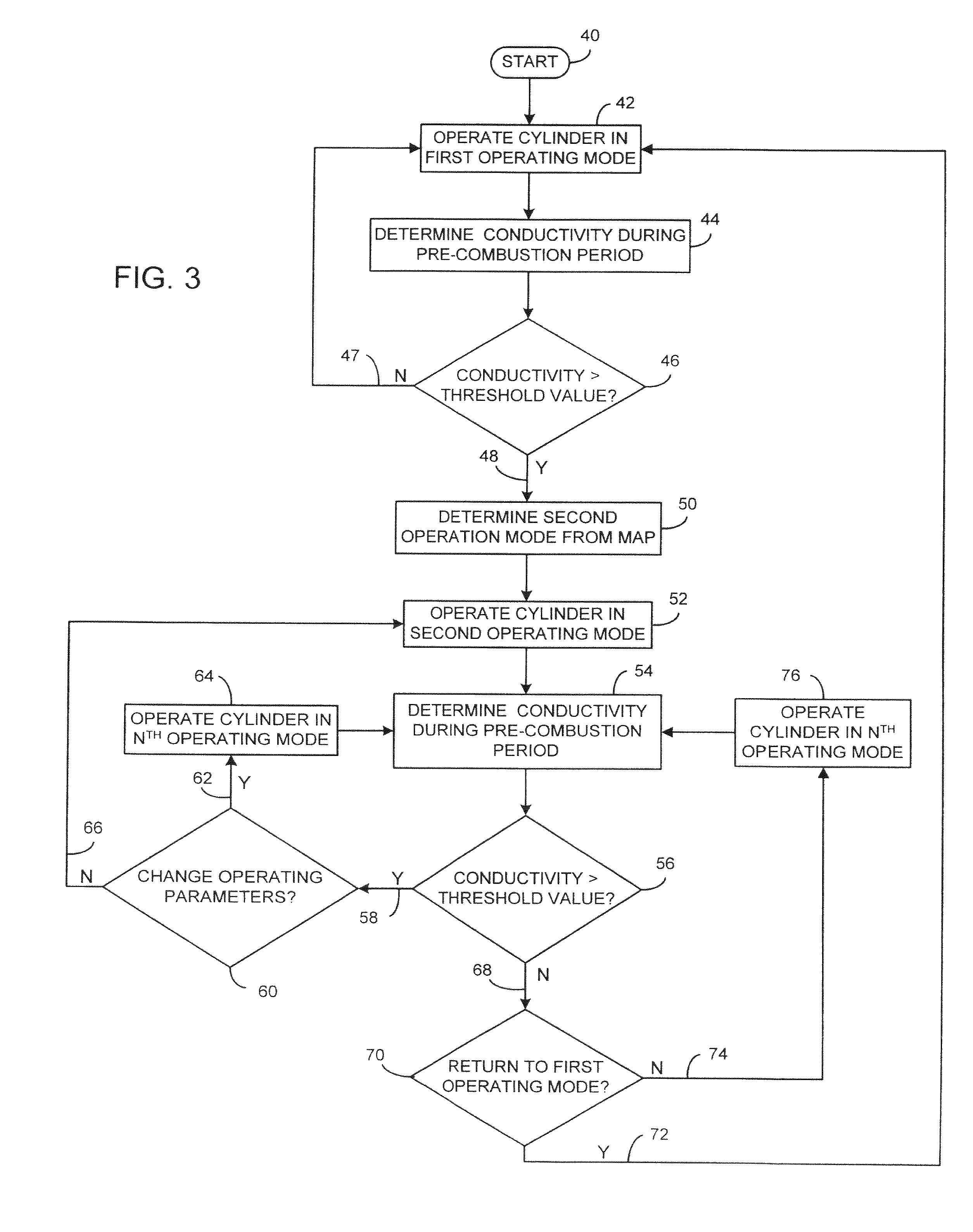
[0010] The present invention provides a system and method to detect and correct spark plug fouling that overcomes the aforementioned drawbacks. An engine control unit (ECU) performs ion gap sensing within the combustion chamber and interprets the results. Specifically, the ECU determines the current between a pair of electrodes within a combustion chamber of a combustion engine prior to, or after, combustion. In a preferred embodiment, the pair of electrodes are spark plug electrodes. The ECU then determines whether the current between the spark plug electrodes is indicative of spark plug fouling. If spark plug fouling is determined, the ECU can modify the mode of operation to correct the spark plug fouling and clean the deposits on the spark plug while the engine is in operation and without operator intervention.

Problems solved by technology

As such, when operating the engine in a stratified operation mode, soot can develop in the combustion chamber from the direct ignition of unvaporized fuel.
Additionally, other operating modes are also known to cause soot production in the combustion chamber.
For example, if the engine is operating in an incorrect heat range or operating with an incorrect air / fuel mixture, soot may also be formed within the combustion chamber.
Over time, the buildup of soot deposited on the electrodes of the spark plug can interfere with the spark across the electrodes.
This buildup of soot, known as spark plug fouling, can cause the engine to misfire.
The result is a loss of power provided by the engine.

Method used


Image

  • System and method to detect and correct spark plug fouling in a marine engine
  • System and method to detect and correct spark plug fouling in a marine engine
  • System and method to detect and correct spark plug fouling in a marine engine

Examples


Embodiment Construction

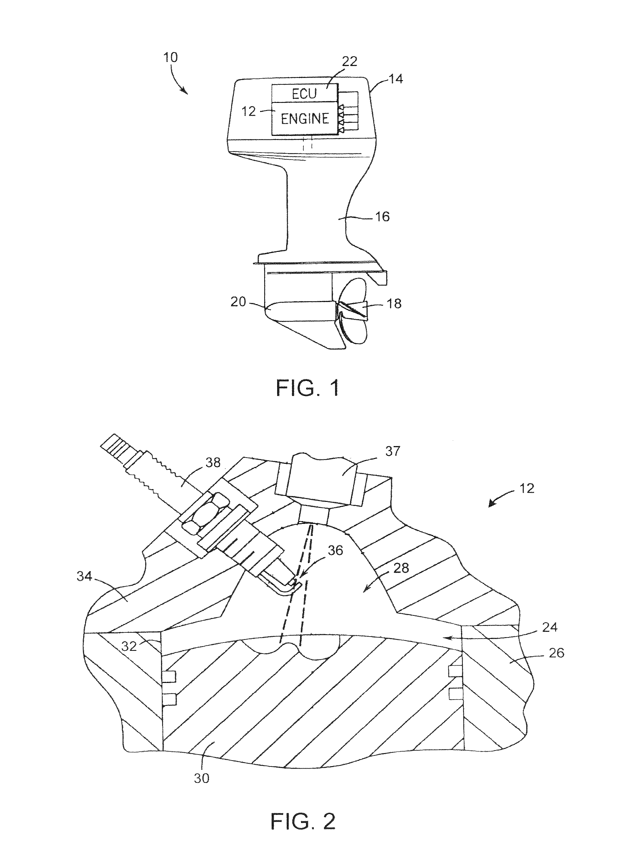
[0021] The present invention relates to internal combustion engines, and preferably, those incorporating direct fuel injection in a spark-ignited gasoline-type engine. In a preferred embodiment, the engine is a two-stroke injection engine. FIG. 1 shows an outboard motor 10 having one such engine 12. The engine 12 is housed in a powerhead 14 and supported on a mid-section 16 configured for mounting on the transom of a boat (not shown) in a known conventional manner. An output shaft of the engine 12 is coupled to a drive propeller 18 extending rearwardly of a lower gearcase 20 via the mid-section 16. The engine 12 is controlled by an electronic control unit (ECU) 22. While the present invention is shown in FIG. 1 as being incorporated into an outboard motor, the present invention is equally applicable with many other engine applications such as inboard motors, motorcycles, scooters, snowmobiles, personal watercrafts, all-terrain vehicles, lawn maintenance equipment, etc.

[0022] Referr...


PUM


Abstract

A system and method for operating a combustion engine including a combustion chamber operable in at least a first operating mode and second operating mode. An engine control unit (ECU) performs conductivity sensing within the combustion chamber and interprets the results. Specifically, the ECU determines the current between a pair of spark plug electrodes placed within a combustion chamber of a combustion engine prior to, or after, combustion. The ECU determines whether the current between the pair of electrodes is indicative of spark plug fouling. If spark plug fouling is determined, the ECU can modify the mode of operation to correct the spark plug fouling and clean the deposits on the spark plug while the engine is in operation and without operation intervention.

Description

CROSS REFERENCE To RELATED APPLICATIONS [0001] The present invention claims the benefit of U.S. Ser. No. 60 / 481,168 filed Aug. 1, 2003.BACKGROUND OF INVENTION [0002] The present invention relates generally to internal combustion engines, and more particularly, to a system and method of detecting spark plug fouling and switching an operation mode of the internal combustion engine to correct any spark plug fouling that is detected. [0003] In general, fuel-injected engines include a fuel injector that provides a fine mist of fuel that mixes with combustion generating gases, that generally comprise a mixture of fresh air and any remaining exhaust gases. Ideally, this mixture is compressed and spark ignited. The spark ignition is typically provided by a spark plug. The spark plug is essentially a pair of electrodes disposed within a combustion chamber and separated by an air gap. One spark plug electrode is connected to an intermittent voltage potential and the other is connected to an e...

Claims


Application Information

Patent Timeline
IPC IPC(8): F02D41/00F02D41/30F02D41/34F02P17/12
CPCF02D41/008F02D41/3029F02P2017/125F02P17/12F02D41/3076
Inventor MONTGOMERY, DAVID T.
Owner BRP US
Learn More