

Self-operated protection device for pipeline
- Summary
- Abstract
- Description
- Claims
- Application Information
AI Technical Summary
Benefits of technology
Problems solved by technology
Method used
Image

Examples
embodiment 1
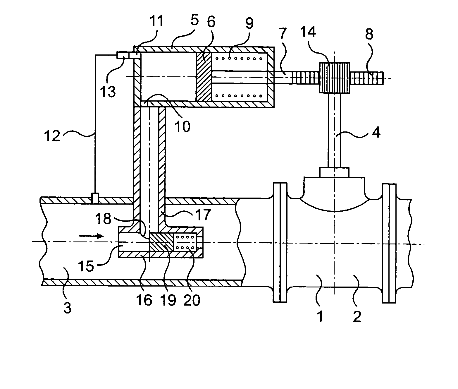
[0026] As shown in FIG. 1, the self-operated protection device for pipeline of the first embodiment of the present invention is comprised of a main valve 1 and a control device. The control device is comprised of a control cylinder 5, a fluid state-sensing device 15 and etc.
[0027] The main valve 1 comprises a valve body 2 having a cavity of a conventional shape and is connected to a fluid pipe 3 in a conventional manner. On the upper end of the valve body there may be provided a valve cover. The valve body can be integral with the valve cover as usual, or they can be separate members and coupled with each other through a flange. The main valve stem 4 of the main valve can be fixedly connected to the main valve core of the main valve, and the main valve with such a structure can be a ball valve, a control valve, a stop valve and etc. The main valve stem 4 can also be rotatably connected to the valve core of the main valve, the valve core being able to reciprocate. The main valve wit...
embodiment 2
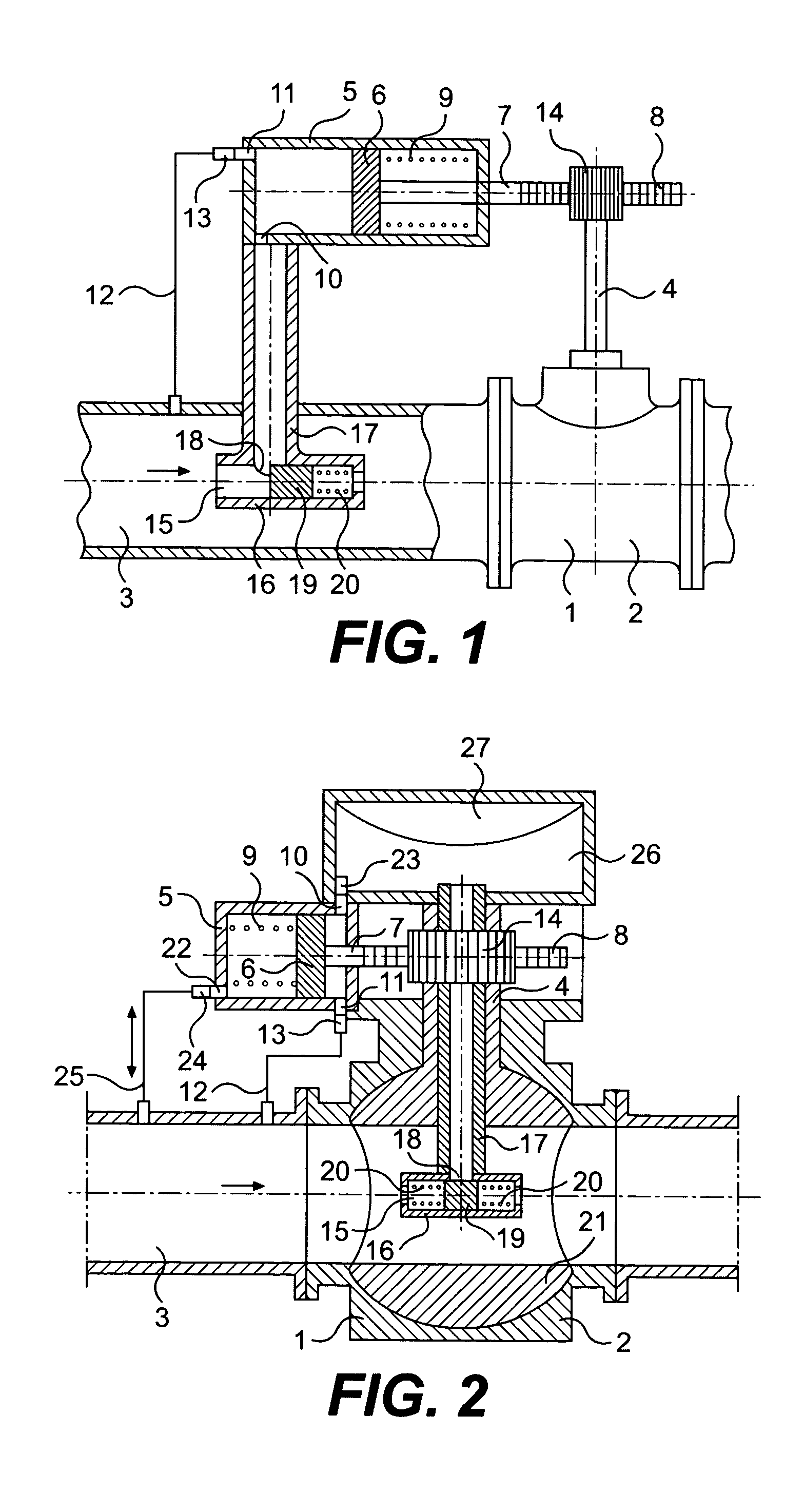
[0034] As shown in FIG. 2, the self-operated protection device for pipeline of the second embodiment of the invention is comprised of a main valve and a control device, the control device being comprised of a control cylinder 5, a flow state-sensing device and etc.
[0035] The structure of the main valve 1 of the second embodiment is substantially the same as that of the first embodiment. A ball valve is used as the main valve, the main valve stem 4 is formed into a circular tube, and the tube is communicated with the flow passage of the main valve core 21.
[0036] The structure of the control cylinder 5 of the second embodiment 2 is substantially the same as that of the first embodiment 1. The control cylinder is transversely arranged and is connected to the valve cover on the upper end of the main valve on the left side of the valve cover. At the right end of the control cylinder there are a cylinder port 10 and a cylinder port 11, and at the left end there is a cylinder port 22. At...
PUM
 Abstract
Description
Claims
Application Information