Protective enclosure with a line-out device adapted for use with electronic componentry

Inactive Publication Date: 2005-02-03
CASE LOGIC
View PDF29 Cites 20 Cited by
  • Summary
  • Abstract
  • Description
  • Claims
  • Application Information

AI Technical Summary

Benefits of technology

[0012] It is a further aspect of the present invention that pockets are provided to store items in the water resistant environment. In one embodiment of the present invention, pockets or sleeves are provided that are capable of receiving a plurality of CDs. Alternatively, other pockets on the inside and outside of the enclosure may be employed to protect items such as keys, money, ski lift passes, driver's licenses, credit cards, etc., from damage or loss.
[0013] It is still yet another aspect of the present invention to provide a protective enclosure that is constructed from known materials and thus inexpensive to manufacture. For example, one resilient embodiment of the present invention is constructed with one or a combination of water resistant materials such as nylon, Gore-TEX®, polypropylene, polyethylene, rubber, treated leather, elastic, and/or plastic. One skilled in the art will appreciate that any resilient material with water resistant properties, may be employed without departing from the scope of the invention. In addition, padding such as foam rubber, is preferably added in various predetermined locations to increase the impact resistance of the enclosure. Alternatively, another embodiment of the present invention is constructed from rigid materials that further increase the impact protection aspect of the present invention. Finally, the enclosure of the present invention may be made in a pl

Problems solved by technology

Depending on the material of construction, many traditional enclosures provide limited protection from impacts, scratches, and fluids.
Unfortunately, in order to provide such protection from the outside elements, the enclosure must be sealed, thereby preventing or restricting access to the electronic device.
However, to gain access to connection ports on the electronic device, the enclosure must be opened thus making the contents more susceptible to damage, especiall

Method used


Image

  • Protective enclosure with a line-out device adapted for use with electronic componentry
  • Protective enclosure with a line-out device adapted for use with electronic componentry
  • Protective enclosure with a line-out device adapted for use with electronic componentry

Examples


Example

[0049] To assist in the understanding of the present invention, the following list of components and associated numbering found in the drawings is provided herein: #Component10Protective enclosure14Electronic device storage compartment15Front portion of enclosure16Rear portion of enclosure17Transparent material18Selective interconnection means22Sheath24Aperture26Line-out-device28Male end of line-out device30Female end of line-out device32Flexible seal34Threaded interface36Storage pocket40Panel42Securing location44Strap46Housing48Flange

[0050] It should be understood that the drawings are not necessarily to scale. In certain instances, details which are not necessary for an understanding of the invention or which render other details difficult to perceive may have been omitted. It should be understood, of course, that the invention is not necessarily limited to the particular embodiments illustrated herein.

DETAILED DESCRIPTION

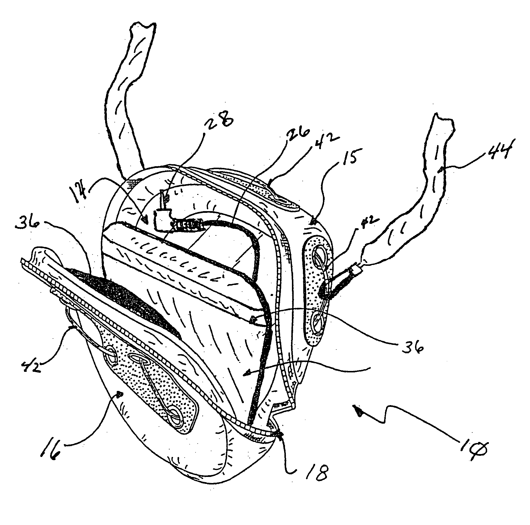
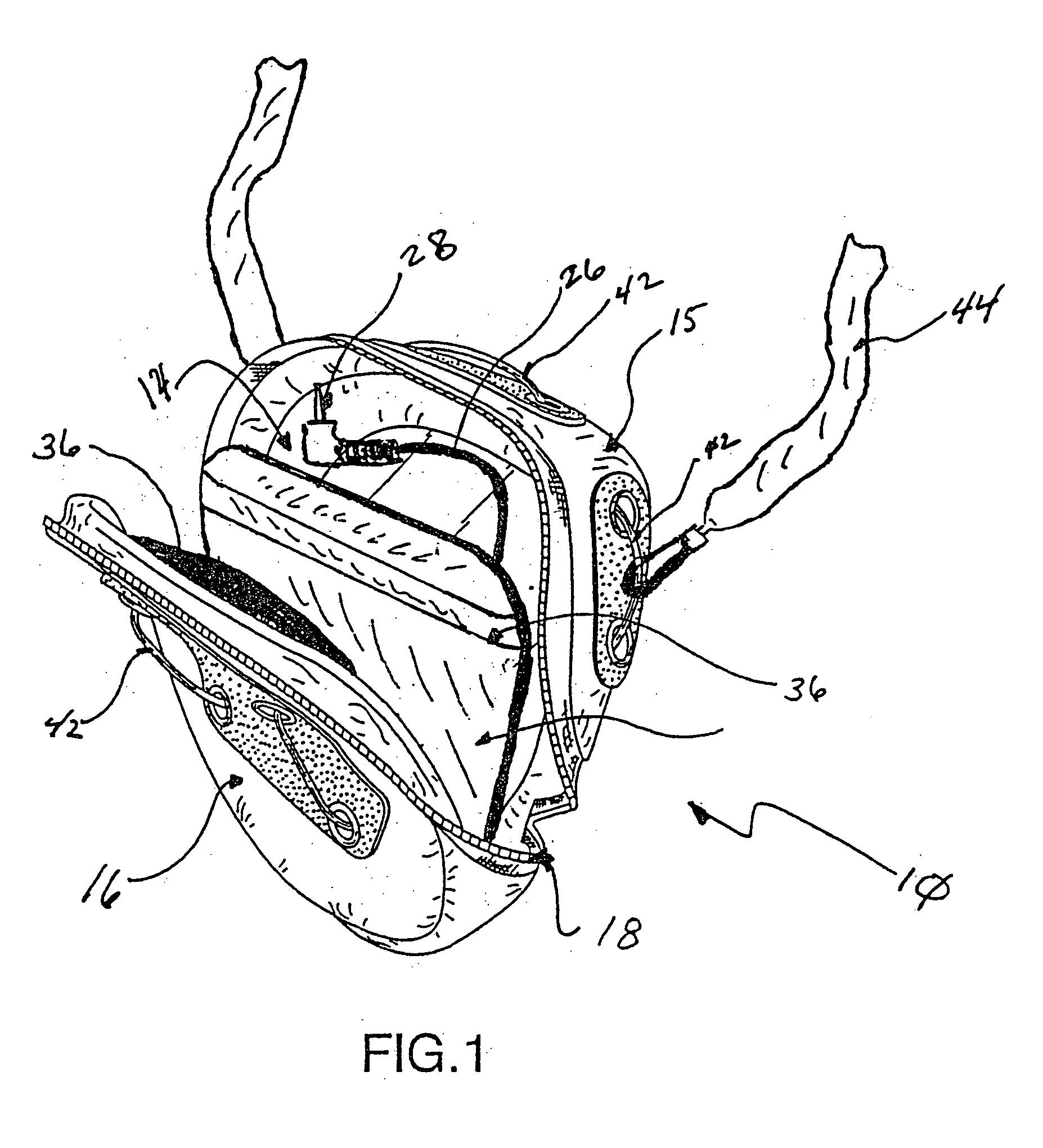
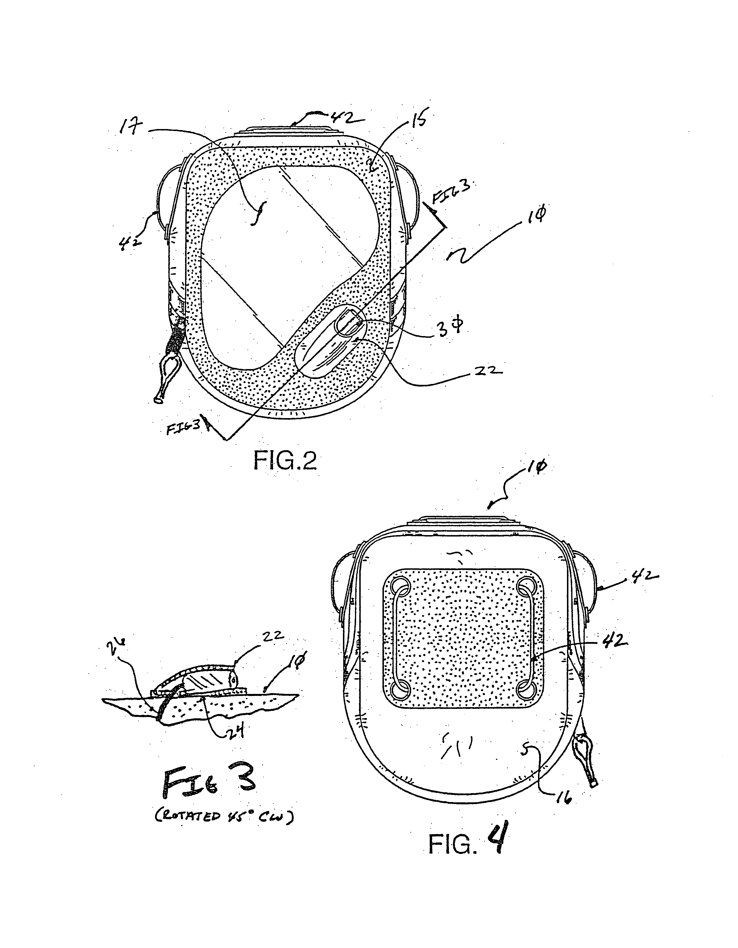
[0051]FIGS. 1-19 depict an enclosure for securing an ele...


PUM


Abstract

A protective enclosure capable of storing an electronic device while protecting it from damage emanating from impacts, impingements, dust and moisture is provided herein. More specifically, the present invention allows a user to use a portable electronic device without requiring the user to open the enclosure and expose the contents to inclement weather.

Description

[0001] This application is a continuation-in-part of U.S. patent application Ser. No. 10 / 409,463, filed Apr. 7, 2003, which claims the benefit of U.S. Design Patent Application Ser. No. 29 / 171,089, now Design Patent D481,865, filed Nov. 15, 2002, and U.S. Provisional Patent Application Ser. No. 60 / 438,916, filed Jan. 8, 2003, all pending applications and issued patents being incorporated by reference in their entirety herein.FIELD OF THE INVENTION [0002] The present invention relates to apparatus that secure and protect electronic devices such as a compact disc players from impacts and water damage, and which allows a user to gain limited access to the enclosure without jeopardizing the water resistant integrity of the device. More specifically, in one embodiment of the present invention an enclosure is provided that is adapted to secure a portable compact disc (hereinafter “CD”) player and a plurality of CDs that includes an external connection port for a user interface, such as a ...

Claims


Application Information

Patent Timeline
IPC IPC(8): A45C13/00A45C15/00A45F3/00A45F5/00G11B33/02H05K9/00
CPCA45C13/008A45C2011/001A45C2011/002A45F5/00G11B33/025A45F5/021A45F2003/002A45F2005/006A45F2200/0508A45F5/02
Inventor HASSETT, ERIC S.
Owner CASE LOGIC
Why Eureka
Try Eureka