
Filler material for use in welding of Mg-contained aluminum alloy die-cast members, welding method, and welded article

a technology of alloy die-cast members and filler materials, which is applied in the field of filler materials, can solve the problems of deterioration of strength, increased cost, and substantial increase in manufacturing costs

Inactive Publication Date: 2005-02-03
NISSAN MOTOR CO LTD +1
View PDF3 Cites 22 Cited by
  • Summary
  • Abstract
  • Description
  • Claims
  • Application Information

AI Technical Summary

Benefits of technology

[0021] The preferred embodiments of the present invention have been developed in view of the above-mentioned and / or other problems in the related art. The preferred embodiments of the present invention can significantly improve upon existing methods and / or apparatuses.
[0022] Among other potential advantages, some embodiments can provide a filler material capable of suppressing generation of blowholes in a welded portion to increase the strength of the welded portion at the time of welding joining members including at least one aluminum alloy die-cast member containing Mg.
[0023] Among other potential advantages, some embodiments can provide a welding method using the aforementioned filler material and a welded article welded by using the aforementioned filler material.
[0025] In this filler material, the Al—K—F series flux is contained by 2 to 4 mass % with respect to the entire filler material. Therefore, in cases where metal members including at least one aluminum die-cast member containing Mg are welded using the filler material, the generation of blowholes in the welded portion due to gases contained in the die-cast member can be suppressed. Furthermore, the escaping of the evaporated Mg from the molten portion can be accelerated, which in turn suppresses the generation of blowholes in the welded portion due to the evaporation of Mg.

Problems solved by technology

However, merely replacing conventional iron material with aluminum alloy causes a substantially increased manufacturing cost.
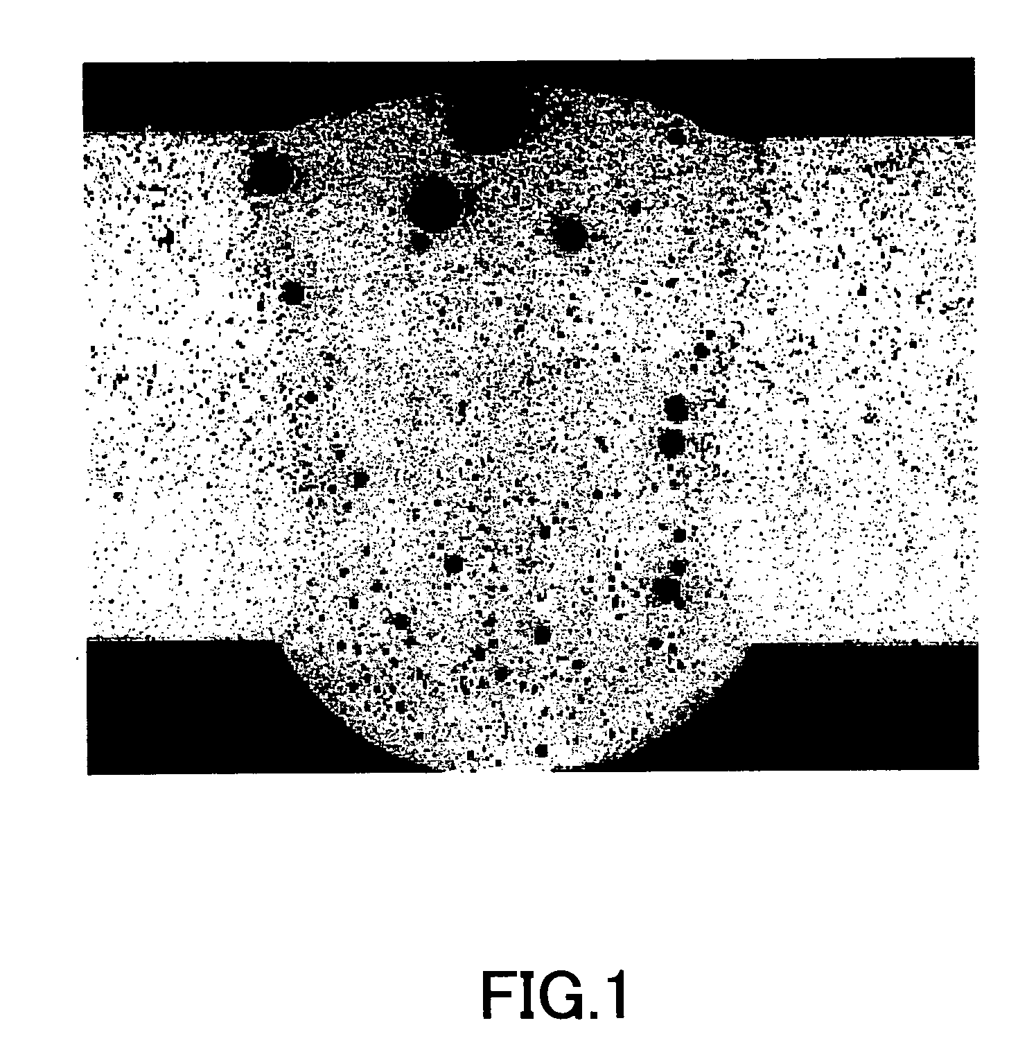
When the aforementioned welding members such as aluminum alloy die-cast members are welded, there are problems that a large amount of blowholes will be generated in the welded portion to cause a deterioration of the strength.
Although the generation of the aforementioned blowholes can be prevented by strictly controlling the gas content in the die-cast member, this requires to improve the quality of die-cast member, resulting in an increased cost.
This problem occurs not only at the time of welding two welding members including at least one aluminum alloy die-cast member but also at the time of performing bead-on welding for the purpose of improving the surface quality of welding members.
However, even in cases where non-heat treatment type aluminum die-cast members are welded by using filler material having the aforementioned blowhole generation suppressing effect, prescribed blowhole generation suppressing effect could not be attained.

Method used


Image

  • Filler material for use in welding of Mg-contained aluminum alloy die-cast members, welding method, and welded article
  • Filler material for use in welding of Mg-contained aluminum alloy die-cast members, welding method, and welded article
  • Filler material for use in welding of Mg-contained aluminum alloy die-cast members, welding method, and welded article

Examples


examples

[0056] Hereinafter, Examples of the present invention will be explained.

[0057] (1) Welding Member (Base Member)

[0058] In Examples, an Al-3.5 mass % Mg-1.5 mass % Si-1.3 mass % Mn alloy was used. The manufacturing method was as follows.

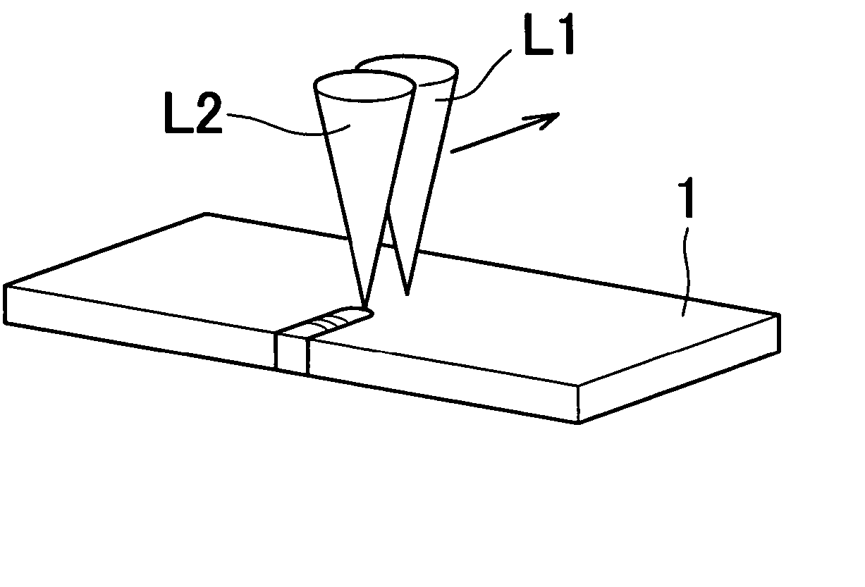
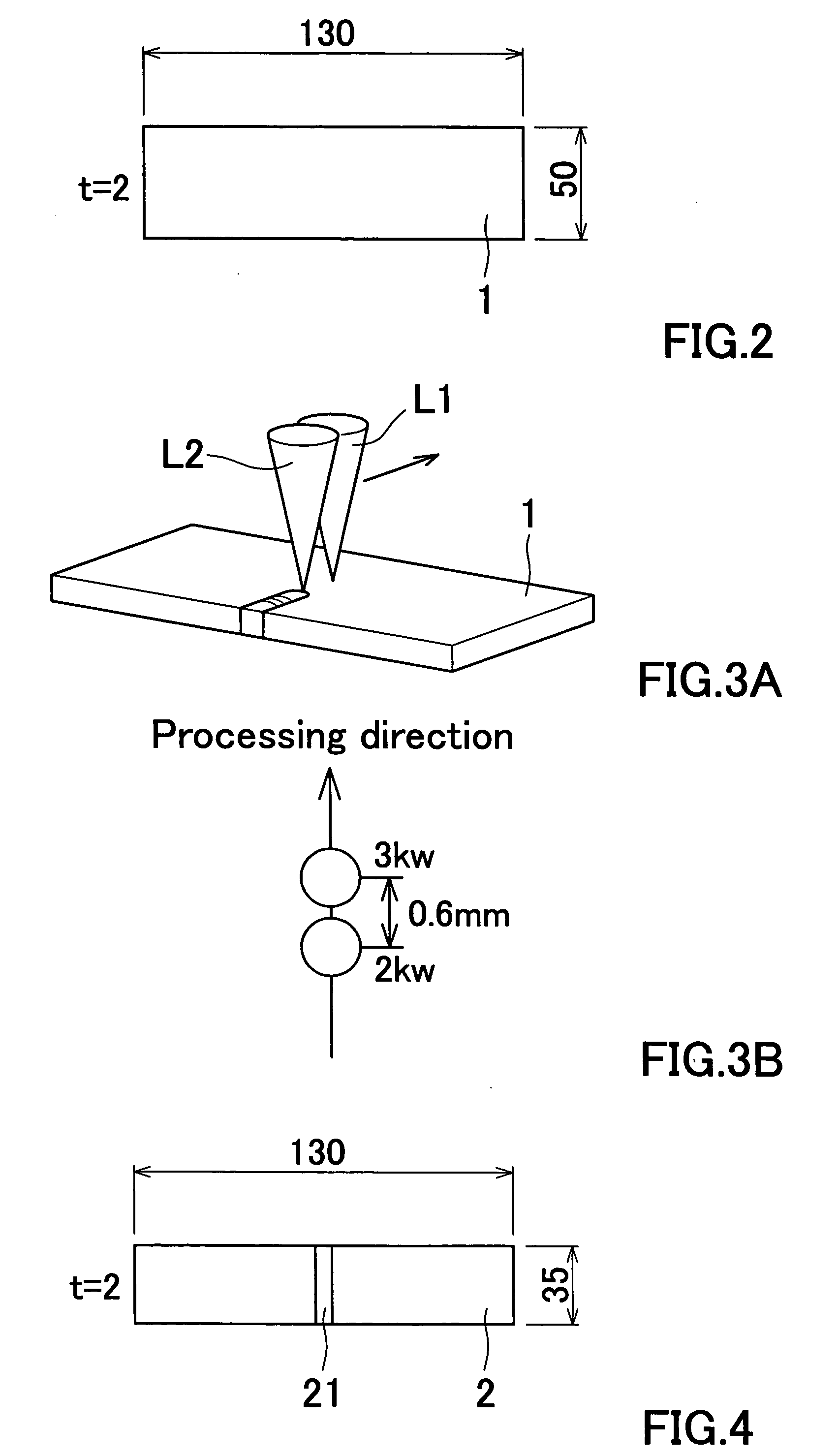
[0059] The aforementioned material was molten at the temperature of 720° C., and then subjected to a bubbling treatment with argon gas for the purpose of removing intermediates and gases. Thereafter, a test piece was obtained by a vacuum die casting method. The die-casting was performed by using a vacuum die-casting machine having a mold clamping force of 320 tons as follows. After applying powder releasing agent to die assemblies, the casting was performed at the casting pressure of 60 MPa and high-speed injection speed of 4 m. The temperature of the molten metal at the time of casting was 700° C. The welding member 1 had a flat plate shape of 130 mm length×50 mm width×2 mm thickness.

[0060] The gas content of the manufactured welding member 1 was ...


PUM

PropertyMeasurementUnit
temperatureaaaaaaaaaa
length×50aaaaaaaaaa
temperatureaaaaaaaaaa

Abstract

An aluminum alloy filler material for use in welding of metal members including at least one aluminum die-cast member containing Mg includes an aluminum or an aluminum alloy as base material and Al—K—F series flux. The Al—K—F series flux is contained by 2 to 4 mass % with respect to the entire filler material.

Description

[0001] This application claims priority under 35 U.S.C. § 119 to Japanese Patent Applications No. 2003-176313 filed on Jun. 20, 2003 and U.S. Provisional Application No. 60 / 482,500 filed on Jun. 26, 2003, the entire disclosure of which are incorporated herein by reference in their entireties. CROSS REFERENCE TO RELATED APPLICATIONS [0002] This application is an application filed under 35 U.S.C. § 111(a) claiming the benefit pursuant to 35 U.S.C. § 119(e)(1) of the filing date of U.S. Provisional Application No. 60 / 482,500 filed on Jun. 26, 2003 pursuant to 35 U.S.C. § 111(b).BACKGROUND OF THE INVENTION [0003] 1. Field of the Invention [0004] The present invention relates to a filler material to be used at the time of welding aluminum alloy die-cast members by laser welding for example. It also relates to a welding method using such filler material and a welded article. [0005] 2. Description of Related Art [0006] The following description sets forth the inventor's knowledge of relate...

Claims


Application Information

Patent Timeline
Patent Type & Authority Applications(United States)
IPC IPC(8): B23K26/06B23K26/14B23K26/24B23K26/32B23K35/02B23K35/28B23K35/36
CPCB23K26/0604B23K26/0608B23K26/1458B23K26/24B23K26/3226B23K2203/10B23K35/286B23K35/3605B23K35/3611B23K2201/18B23K35/0261B23K26/32B23K26/1462B23K2101/18B23K2103/10
Inventor TSUSHIMA, KENJIHASHIMOTO, TAKENORI
Owner NISSAN MOTOR CO LTD
Learn More