High-frequency composite component

a composite component and high-frequency technology, applied in the direction of electrical equipment, transmission, coupling devices, etc., can solve the problems of increasing the area occupied by the circuit, increasing the loss of signal, and requiring a tedious job, so as to reduce the cost and the size of the overall system, simplify the circuit from the antenna, and reduce the cost and the effect of siz

Inactive Publication Date: 2005-02-03
SEIKO EPSON CORP
View PDF6 Cites 4 Cited by
  • Summary
  • Abstract
  • Description
  • Claims
  • Application Information

AI Technical Summary

Benefits of technology

[0023] According to the invention configured as described above, it is possible to simplify the circuits from the antenna to the input side of the high-frequency amplifier circuit; suppress a loss in the signal on the way; and reduce the cost and the size, w

Problems solved by technology

Also, because the conventional high-frequency composite component includes the balanced-to-unbalanced circuit, it is possible to transform a balanced signal to an unbalanced signal and vice versa.
However, due to the problems in terms of power efficiency and the characteristic, it is typical to use plural high-frequency amplifiers, one for each usable frequency.
Hence,

Method used


Image

  • High-frequency composite component
  • High-frequency composite component
  • High-frequency composite component

Examples


Embodiment Construction

[0031] An embodiment of the invention will now be described with reference to the accompanying drawings.

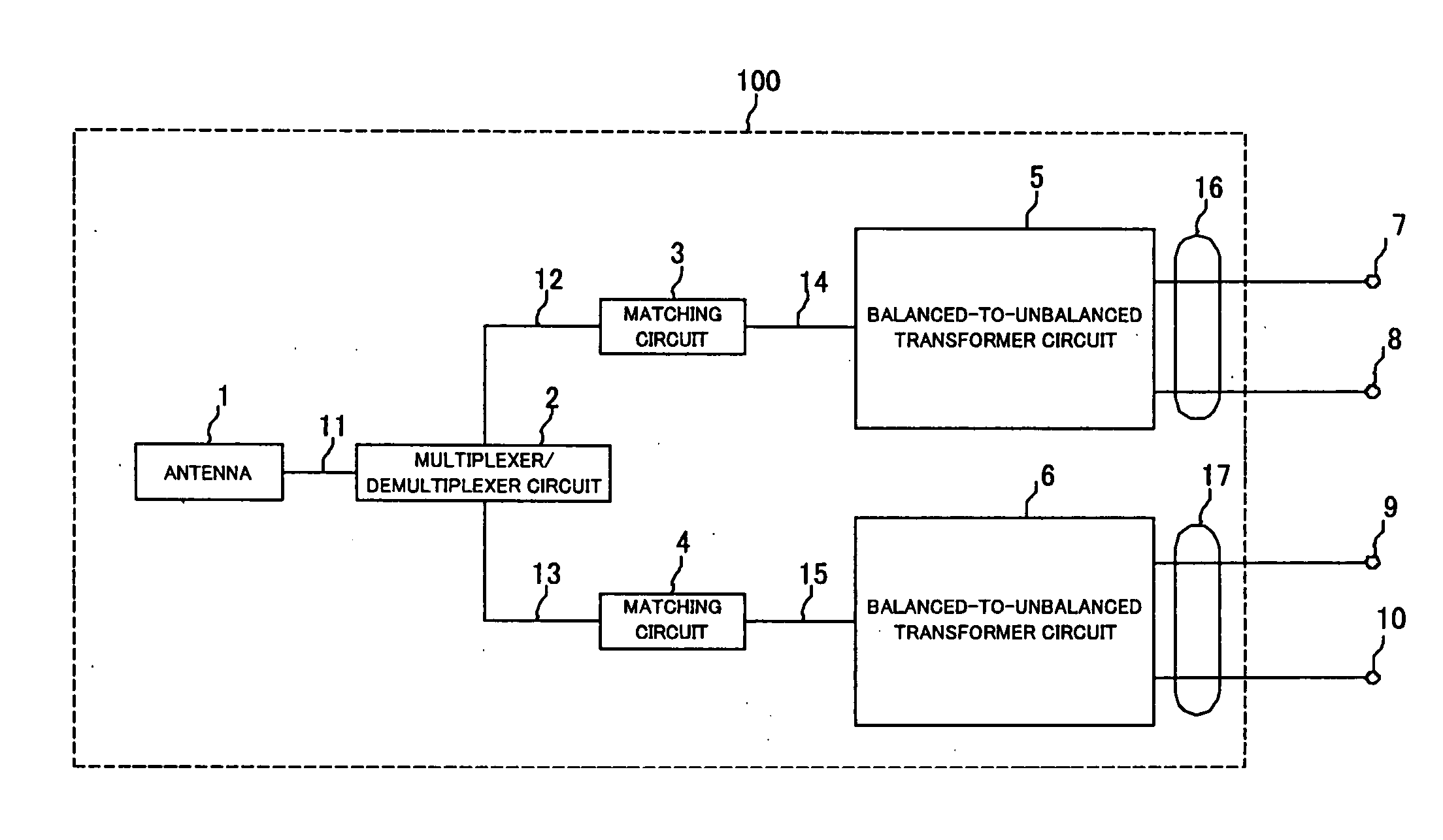
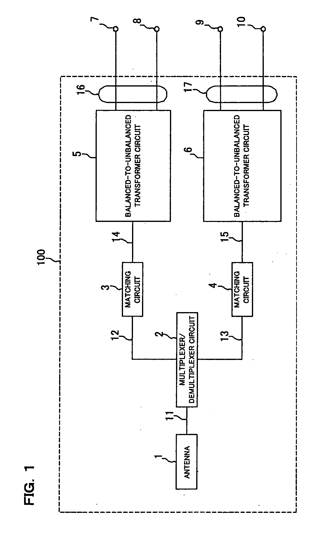
[0032]FIG. 1 is a block diagram showing the circuitry of a high-frequency composite component according to one embodiment of the invention.

[0033] A high-frequency composite component 100 of this embodiment is applied to a portion relating to, for example, wireless communications in a wireless LAN, and includes, as shown in FIG. 1, an antenna 1, a multiplexer / demultiplexer circuit 2, matching circuits 3 and 4, balanced-to-unbalanced transformer circuits (baluns) 5 and 6, and input and output terminals 7 through 10.

[0034] The terminal of the antenna 1 is electrically connected to one terminal of the multiplexer / demultiplexer circuit 2 via an unbalanced line path 11. Another first terminal of the multiplexer / demultiplexer circuit 2 is electrically connected to one terminal of the matching circuit 3 via an unbalanced line path 12. Still another second terminal of the multiplexer / de...


PUM


Abstract

A high-frequency composite component is provided by placing an antenna on a multi-layer wiring board, placing a multiplexer/demultiplexer circuit, first and second matching circuits, and first and second balanced-to-unbalanced transformer circuits inside the board respectively, and providing first to fourth input and output terminals on the side surface of the board. The antenna is connected to the multiplexer/demultiplexer circuit via a first unbalanced line path, and the multiplexer/demultiplexer is connected to the first and second matching circuits via second and third unbalanced line paths, respectively. The first and second matching circuits are connected to the first and second balanced-to-unbalanced transformer circuits, respectively, via fourth and fifth unbalanced line paths, respectively. The respective balanced terminals of the first and second balanced-to-unbalanced transformer circuits are connected to the first and second, and third and fourth input and output terminals, respectively, via first and second balanced line paths, respectively.

Description

RELATED APPLICATIONS [0001] This application claims priority to Japanese Patent Application No. 2003-192287 filed Jul. 4, 2003 which is hereby expressly incorporated by reference herein in its entirety. BACKGROUND [0002] 1. Technical Field [0003] The invention relates to a high-frequency composite component used as part of the front end of a wireless communications device or the like, and is applied to wireless communication systems such as, for example, a wireless LAN system. [0004] 2. Related Art [0005] Conventionally, a high-frequency composite component, such as a mobile phone, including, for example, a balanced-to-unbalanced transformer circuit (balun) and a multiplexer / demultiplexer circuit, which are composed inside a multi-layer wiring board, has been known (for example, see JP-A-2002-217036 (FIG. 1)). [0006] In the high-frequency composite component shown in the conventional example, the multiplexer / demultiplexer circuit processes an unbalanced signal. Hence, the multiplexe...

Claims


Application Information

Patent Timeline
IPC IPC(8): H04B1/3822H04B1/40
CPCH04B1/0057H04B1/52H04B1/406H04B1/006
Inventor WATANABE, TORUTAKADA, YUTAKAINOGUCHI, MAKOTOYAJIMA, ARITSUGUTANAKA, KAZUAKITAKAGI, SHIGEKAZU
Owner SEIKO EPSON CORP
Why Eureka
Try Eureka