Raster engine with multiple color depth digital interface

a digital display interface and raster engine technology, applied in static indicating devices, cathode-ray tube indicators, instruments, etc., can solve the problems of affecting display cost, color displays generally cost more than monochrome displays, and display resolution and quality vary with display resolution and quality, so as to reduce the undesirable visual effects, reduce the cost, and provide flexible interfacing

Inactive Publication Date: 2005-02-03
HANGER SOLUTIONS LLC
View PDF14 Cites 19 Cited by
  • Summary
  • Abstract
  • Description
  • Claims
  • Application Information

AI Technical Summary

Benefits of technology

[0034] The raster engine may further comprise a grayscale look up table control register programmable by the computer system, and a grayscale look up table programmable by the computer system via the grayscale look up table control register. The grayscale generator may further comprise a frame counter, a vertical counter, and a horizontal counter, wherein the grayscale look up table data entries define dithering operation for a pixel value according to the frame counter, the vertical counter, and the horizontal counter. The invention thus provides a grayscale look up table or matrix which is programmable by a user or an application program in order to effectively provide flexible interfa...

Problems solved by technology

The cost of displays varies with the display resolution and quality.
For example, color displays generally cost more than monochrome displays.
The number of pixels, as well as the number of available colors per pixel (bits per pixels) also affects display cost.
The cost of a computer display may be a large percentage of the overall computer system cost.
Although high-end video controllers can provide maximum colors at maximum resolution, there is typically a tradeoff involving memory and bus bandwidth, wherein the higher the resolution, the fewer the available colors.
Conventional techniques, however do not allow flexible application of grayscaling to multiple disparate display types in a single video controller.
Using the video controller to overlay a cursor image on a displayed image is difficult in association with a dual scanned display, where the upper and lower portions of the display screen are scanned in parallel.
Cursor overlaying is particularly difficult where the cursor image location crosses the boundary between the upper and lower portions of the display.
Software cursor overlaying techniques occupy system resources and processor time, which may be unacceptable or undesirable in some applications.
However, the use of software occupies computer system processor time and may ...

Method used


Image

  • Raster engine with multiple color depth digital interface
  • Raster engine with multiple color depth digital interface
  • Raster engine with multiple color depth digital interface

Examples


Embodiment Construction

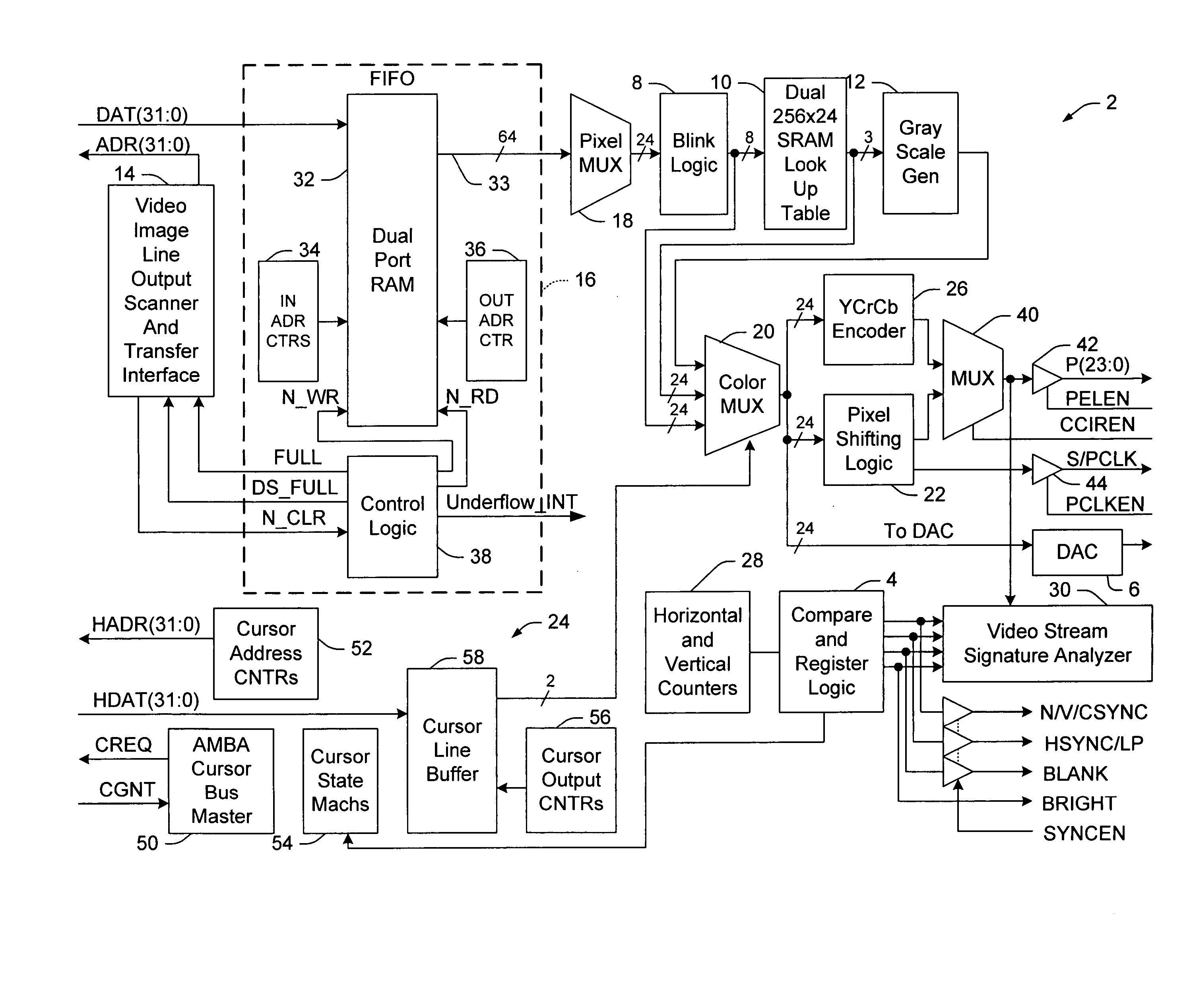
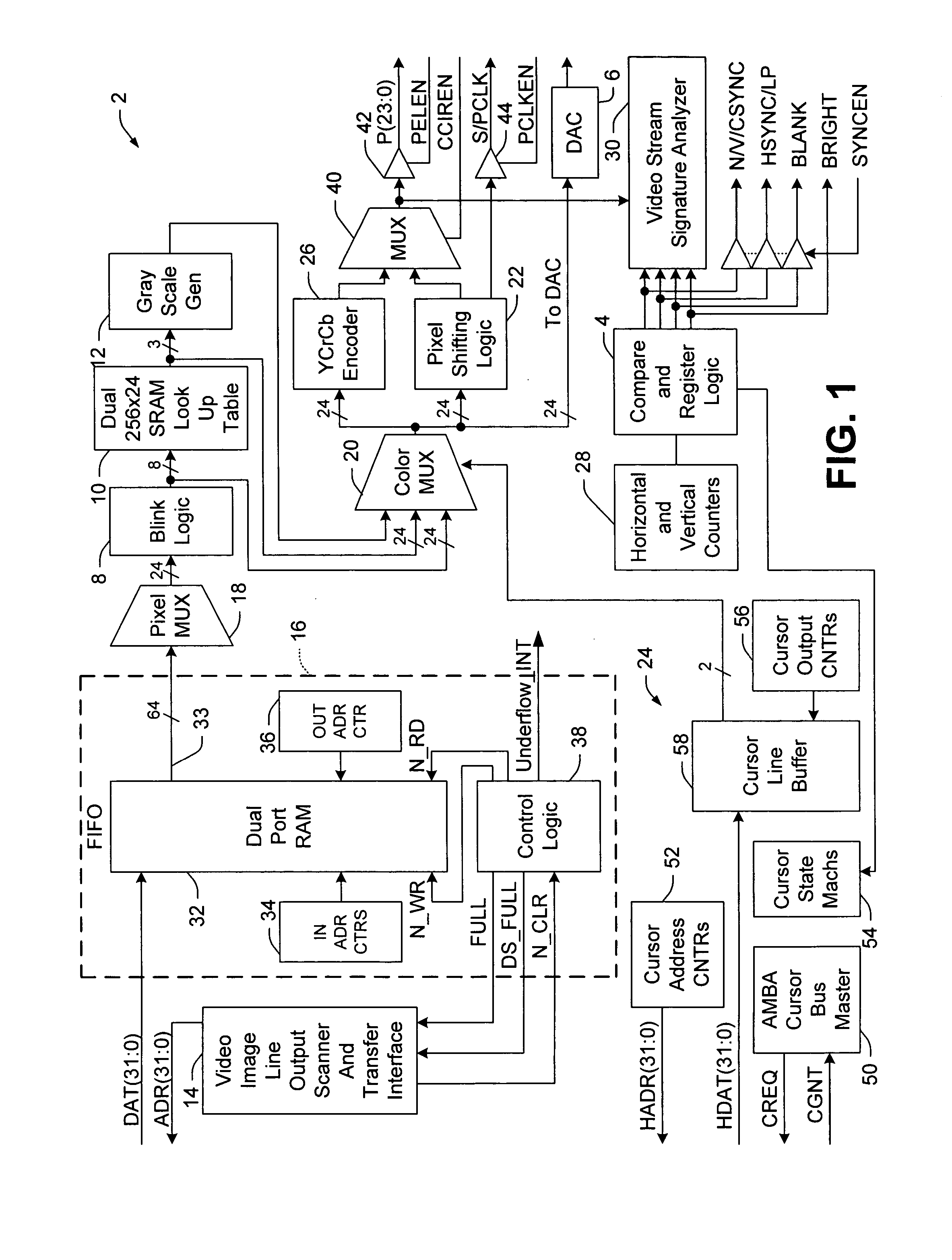
[0073] The following is a detailed description of the present invention made in conjunction with the attached figures, wherein like reference numerals will refer to like elements throughout. According to the invention, an improved raster engine is provided to render video data from a frame buffer to one of a plurality of disparate displays which comprises an integral bounded video signature analyzer, a hardware cursor apparatus supporting dual scanned displays, programmatic support for multiple disparate display types, multi-mode programmable hardware blinking, programmable multiple color depth digital display interface, and programmable matrix controlled grayscale generation.

[0074] Referring now to the drawings, FIG. 1 illustrates an exemplary raster engine 2, which is adapted to provide data and interface signals for a variety of displays, including analog CRTs and digital LCDs (not shown). In addition, the raster engine 2 has fully programmable video interface timing for progres...


PUM


Abstract

An improved raster engine adapted to render video data from a frame buffer to one of a plurality of disparate displays is disclosed which comprises an integral bounded video signature analyzer, a hardware cursor apparatus supporting dual scanned displays, programmatic support for multiple disparate display types, multi-mode programmable hardware blinking, programmable multiple color depth digital display interface, and programmable matrix controlled grayscale generation.

Description

CROSS-REFERENCE TO RELATED APPLICATIONS [0001] This application is a continuation of pending U.S. patent application Ser. No. 09 / 672,637 entitled “RASTER ENGINE WITH MULTIPLE COLOR DEPTH DIGITAL DISPLAY INTERFACE” and filed Sep. 28, 2000, the entirety of which is incorporated by reference.TECHNICAL FIELD [0002] The present invention relates generally to the field of video displays and more particularly to an improved raster engine with a multiple color depth digital display interface. BACKGROUND OF THE INVENTION [0003] Video displays are used in computer systems to present visual images to a user based on video data provided by a computer or other processing device. The display allows a user to effectively receive information from and to interact with application programs running in the system. Such computer systems and displays are employed in numerous business, consumer, entertainment, and industrial settings, including automated industrial control systems. [0004] Displays are ava...

Claims


Application Information

Patent Timeline
IPC IPC(8): G09G5/02G09G5/08G09G5/30G09G5/395G09G5/397
CPCG09G5/08G09G5/30G09G2360/02G09G2310/0221G09G2340/0428G09G5/395
Inventor DOTSON, GARY DANHEIDEBRECHT, THOMAS LLOYD
Owner HANGER SOLUTIONS LLC
Why Eureka
Try Eureka