Optical film having microeplicated structures; and methods
a technology of optical film and micro-eplication, applied in the direction of optical elements, lighting and heating apparatus, instruments, etc., can solve the problems of limited depth function of signals which can be used to generate depth, and achieve the effects of avoiding glare effects, efficient utilization of available light, and improving durability of tools and surface quality
- Summary
- Abstract
- Description
- Claims
- Application Information
AI Technical Summary
Benefits of technology
Problems solved by technology
Method used
Image
Examples
example 2
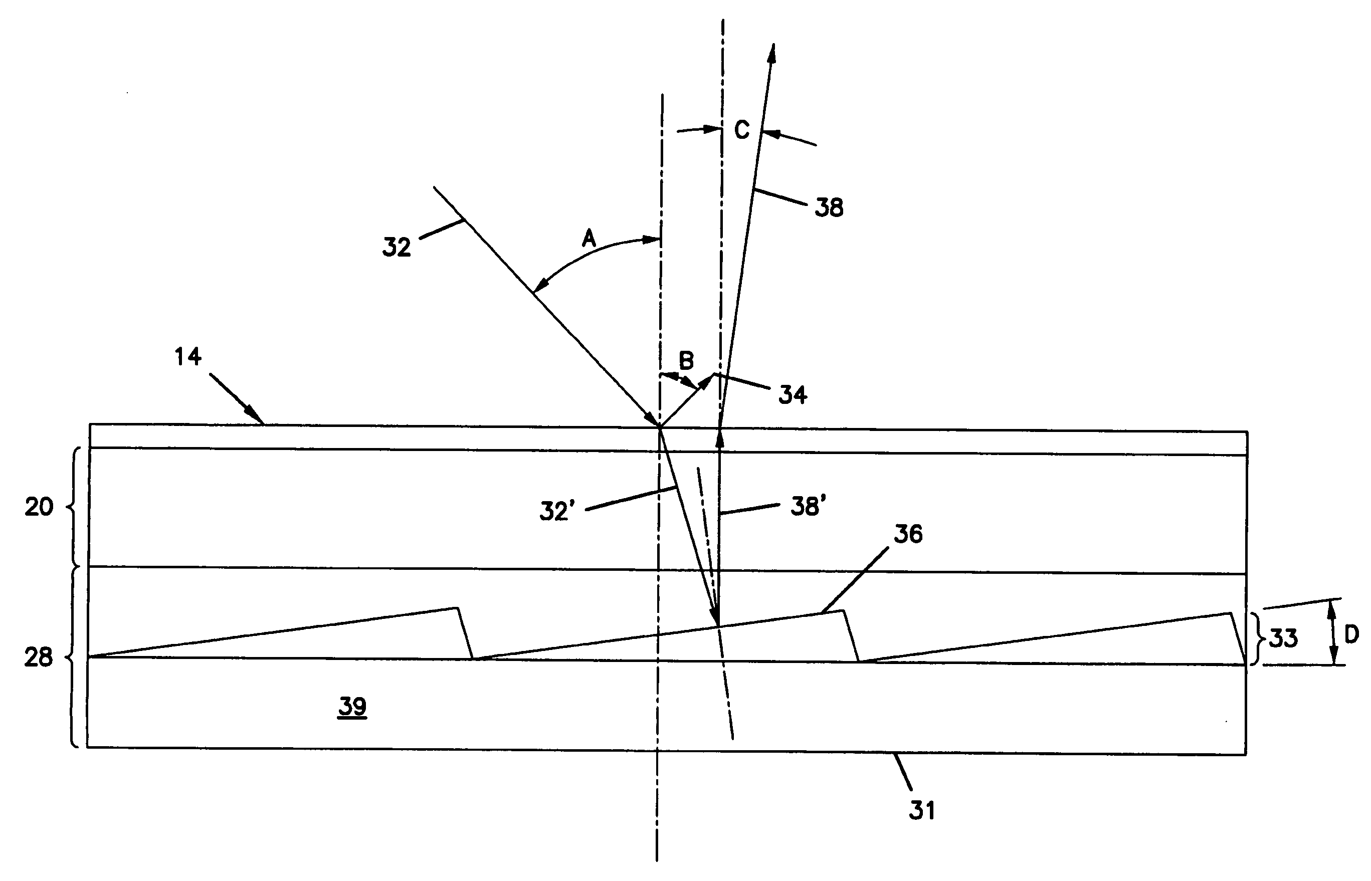
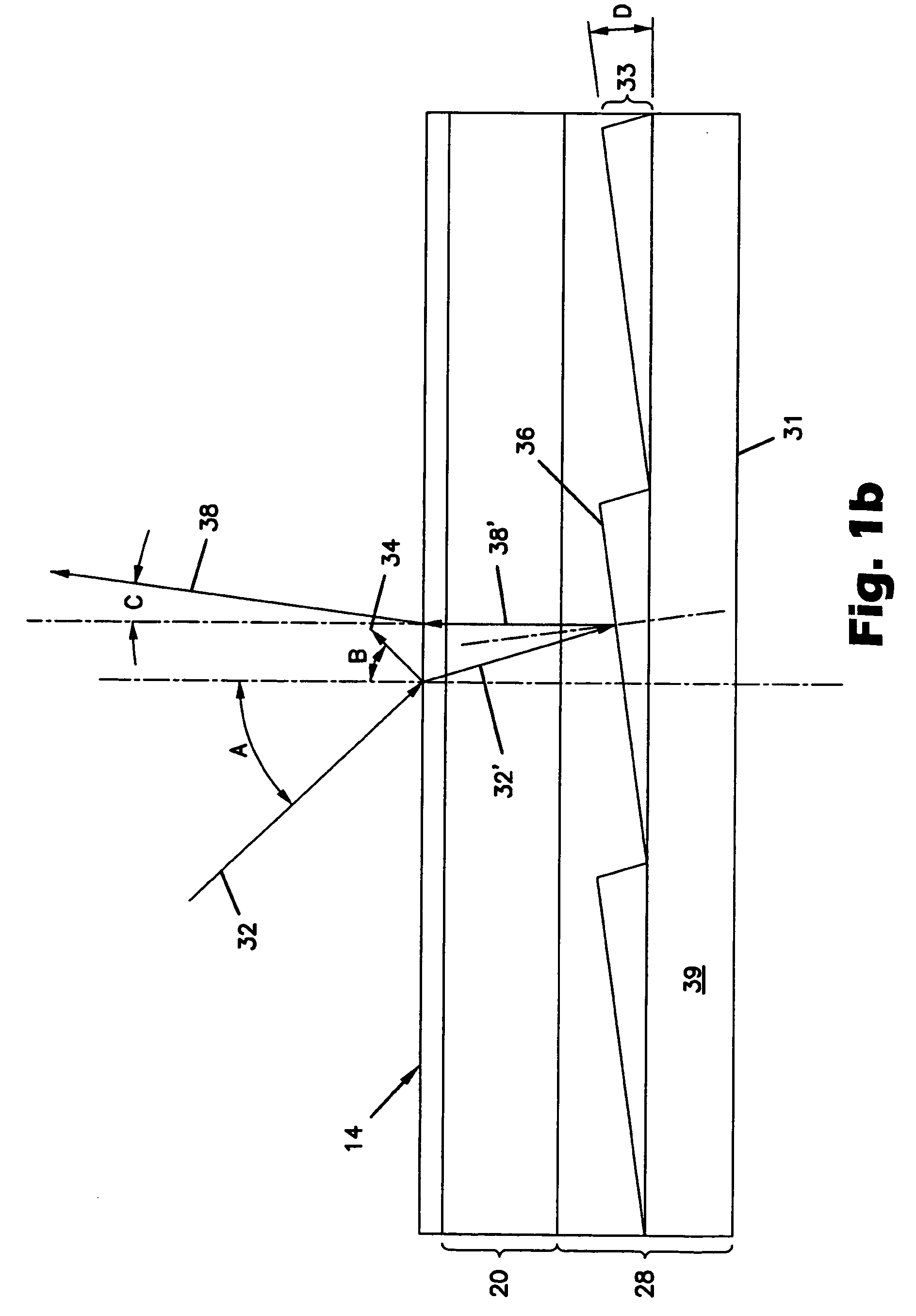
[0113] Variable Facet or Prism Angle
[0114]FIG. 5 is a cross-sectional view of a light directing construction 200, which includes a light directing film 210, according to one aspect of the present invention. This view of light directing film 210 is similar to the orientation shown in FIG. 2, with the y-axis extending across the structure from left to right in the figure, and the z-axis extending top to bottom of the figure. The x-axis extends into the page.
[0115] Light directing film 210 has a smooth surface 212 and a structured surface 214, which create a plurality of prisms 240 having a first prism face 242 and a second prism face 244 that define valleys 243 and peaks 245. First prism face 242 and second prism face 244 form a pair of faces that define a composite. Generally, first prism face 242 is used for reflecting light; second prism face 244 does not participate in light reflectance or direction. Smooth surface 212 of film 210 is adjacent substrate 220. Overlying light direc...
examples 3a and 3b
[0121] Curved, Non-Linear Facets
[0122]FIG. 6 is a cross-sectional view of a light directing construction 300 according to another aspect of the present invention. This view of light directing construction 300, and light directing film 310, is similar to the orientation shown in FIG. 2, with the y-axis extending across the structure from left to right in the figure, and the z-axis extending top to bottom of the figure. The x-axis extends into the page.
[0123] Light directing construction 300 includes a light directing film 310 having a smooth surface 312 and a structured surface 314, which includes a plurality of prisms 340 having a first prism face 342 and a second prism face 344 that define valleys 343 and peaks 345. Smooth surface 312 is adjacent substrate 320. Overlying light direction film 310 is a metal coating 330 and a diffuser layer 335 having a low concentration of glass or polymeric beads 336 to mask artifacts and defects.
[0124] First prism face 342, rather than being a ...
example 4
[0128] Segmented Face having Linear or Curved Segments
[0129]FIG. 9 is a cross-sectional view of a light directing construction 400 according to another aspect of the present invention. Light directing construction 400 includes a light directing film 410 having a smooth surface 412 and a structured surface 414. Light directing film 410 is oriented similar to the orientation shown in FIG. 2, with the y-axis extending across the structure from left to right in the figure, and the z-axis extending top to bottom of the figure. The x-axis extends into the page.
[0130] Light directing film 410 includes a plurality of prisms 440 having a first prism face 442 and a second prism face 444 that define valleys 443 and peaks 445. Smooth surface 412 is adjacent substrate 420. Overlying light direction film 410 is a metal coating 430 and a diffuser layer 435 having a low concentration of glass or polymeric beads 436 to mask artifacts and defects.
[0131] First prism face 442 includes at least two s...
PUM
 Abstract
Description
Claims
Application Information
 - R&D
- Intellectual Property
- Life Sciences
- Materials
- Tech Scout
- Unparalleled Data Quality
- Higher Quality Content
- 60% Fewer Hallucinations
Browse by: Latest US Patents, China's latest patents, Technical Efficacy Thesaurus, Application Domain, Technology Topic, Popular Technical Reports.
© 2025 PatSnap. All rights reserved.Legal|Privacy policy|Modern Slavery Act Transparency Statement|Sitemap|About US| Contact US: help@patsnap.com


