Tilt detection system, tilt detection method and tilt adjustment method

Inactive Publication Date: 2005-02-03
TEAC CORP
View PDF11 Cites 2 Cited by
  • Summary
  • Abstract
  • Description
  • Claims
  • Application Information

AI Technical Summary

Benefits of technology

[0008] An object of the present invention is to provide a tilt detection system by which it is possible to easily detect the optimum state in tilt adjustment also for radial direction similarly to the case for tangential direction, and to perform the tilt adjustment precisely and easily.
[0013] In this configuration, as a result of a signal being reproduced from an optical disk in which information inverts faster than data having the minimum pulse width recorded in an ordinary optical disk, the quality of the recorded data is degraded, and the quality of the reproduced signal sensitively responds to change in the tilt. Accordingly, even in radial direction, it is easy to detect the optimum state in tilt adjustment similarly to the case of tangential direction, and thus to perform the tilt adjustment precisely and easily.
[0016] decreasing a gain of a low-pass filter limiting a for the highest frequency of predetermined essential frequencies of a reproduced RF signal obtained from the reproduction the signal from the optical disk; and
[0018] In this configuration, the low-pass filter limits the frequency band of the signal obtained through reproducing, and decreases the amplitude of the signal of the above-mentioned highest frequency of the signal obtained through the reproduction. Thereby, the quality of the signal in of the highest frequency is degraded, and the quality of the reproduced signal sensitively responds to change in the tilt. Accordingly, even in radial direction, it is easy to detect the optimum state in tilt adjustment similarly to the case of tangential direction, and to perform the tilt adjustment precisely and easily.
[0022] In this configuration, data of the optical disk in which recording is made at an ordinary speed is reproduced at a speed higher than the ordinary speed. Thereby, the quality of the signal is degraded, and the quality of the reproduced signal sensitively responds to change in tilt. Accordingly, even in radial direction, it is easy to detect the optimum state in tilt adjustment similarly to the case of tangential direction, and to perform the tilt adjustment precisely and easily.

Problems solved by technology

However, when the light beam is not incident on the recording surface of the optical disk at right angles due to inclination of the optical disk and / or inclination of the objective lens, coma aberration is generated.
Thereby, distortion occurs in the reproduced waveform, and jitter occurs, as is well known.
Accordingly, it is difficult to find the optimum state in tilt adjustment, and, thus, to adjust the tilt optimally.

Method used


Image

  • Tilt detection system, tilt detection method and tilt adjustment method
  • Tilt detection system, tilt detection method and tilt adjustment method
  • Tilt detection system, tilt detection method and tilt adjustment method

Examples


first embodiment

[0034]FIGS. 2 through 5 illustrate the present invention.

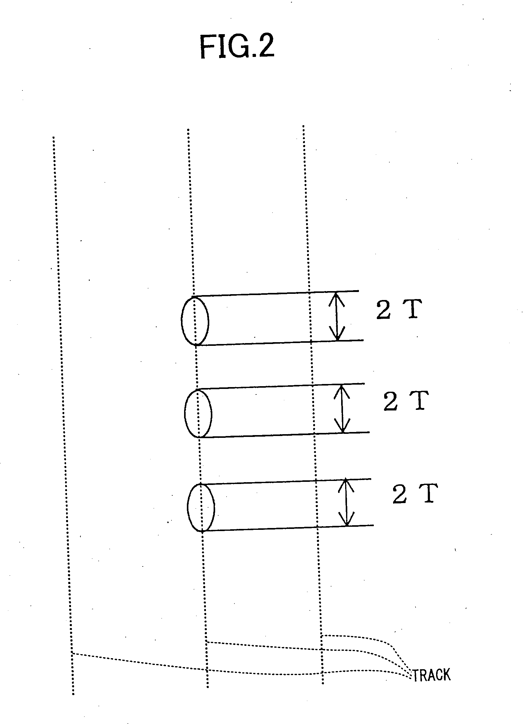
[0035] In the first embodiment of the present invention, a successive 2T patterns, as shown in FIG. 2, are formed at a part of the track of an ordinary CD-ROM disk for the tilt adjustment.

[0036] In the ordinary CD-ROM disks an EFM-modulated signal is recorded in a form of pits. This signal has pulse widths of 3T through 11T where T is a duration corresponding to 1 channel bit. In contrast to this, in the track of the optical disk shown in FIG. 2, in addition to the patterns corresponding to the signal recorded in the ordinary optical disk as mentioned above, the patterns each having the length corresponding to the pulse width 2T is formed which is narrower than the pulse width 3T which is the minimum one of those of the signal recorded in the ordinary optical disk.

[0037]FIG. 3A shows the eye pattern of the RF signal obtained when a reproducing operation is performed on the ordinary optical disk, and FIG. 3B shows the eye pat...

second embodiment

[0056] A second embodiment and a variant embodiment thereof of the present invention will now be described with reference to FIGS. 6, 7A, 7B, 8A and 8B.

[0057] In each of the second embodiment and variant embodiment, the tilt adjustment is performed in a condition in which the gain characteristics of a low-pass filter of an optical disk drive are changed, and, thereby, the reproduction characteristics are made severe.

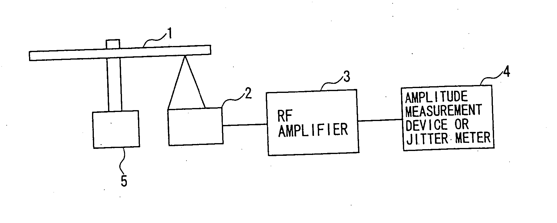
[0058]FIG. 6 shows low-pass filters included in an equalizer of an RF amplifier of the optical disk drive.

[0059] The low-pass filter 11 has the gain characteristics shown in FIG. 7A such that the gain becomes the peak about the frequency corresponding to the above-mentioned 3T. In contrast to this, the low-pass filter 12 has the gain characteristics shown in FIG. 7B such that the gain decreases about the frequency corresponding to 3T.

[0060] As shown in FIG. 6, the low-pass filters 11 and 12 are connected in parallel, and one of them is selected by a change-over switch...

third embodiment

[0080] the present invention will now be described.

[0081] In each of the third embodiment and a variant embodiment thereof, the tilt adjustment is performed in a condition in which an ordinary optical disk is rotated at a rotation speed higher than the ordinary rotation speed, and, thereby, the reproduction characteristics are made severe.

[0082]FIG. 9A shows a circuit configuration of a tilt detection system in an optical disk drive in the third embodiment of the present invention.

[0083] When the rotation speed of the optical disk is increased, the resolution of the thus-obtained reproduced signal is degraded. At this time, the 3T-data pulse having the narrow pulse width is affected thereby remarkably, the reproduced amplitude decreases, and both jitter amount and error rate increase.

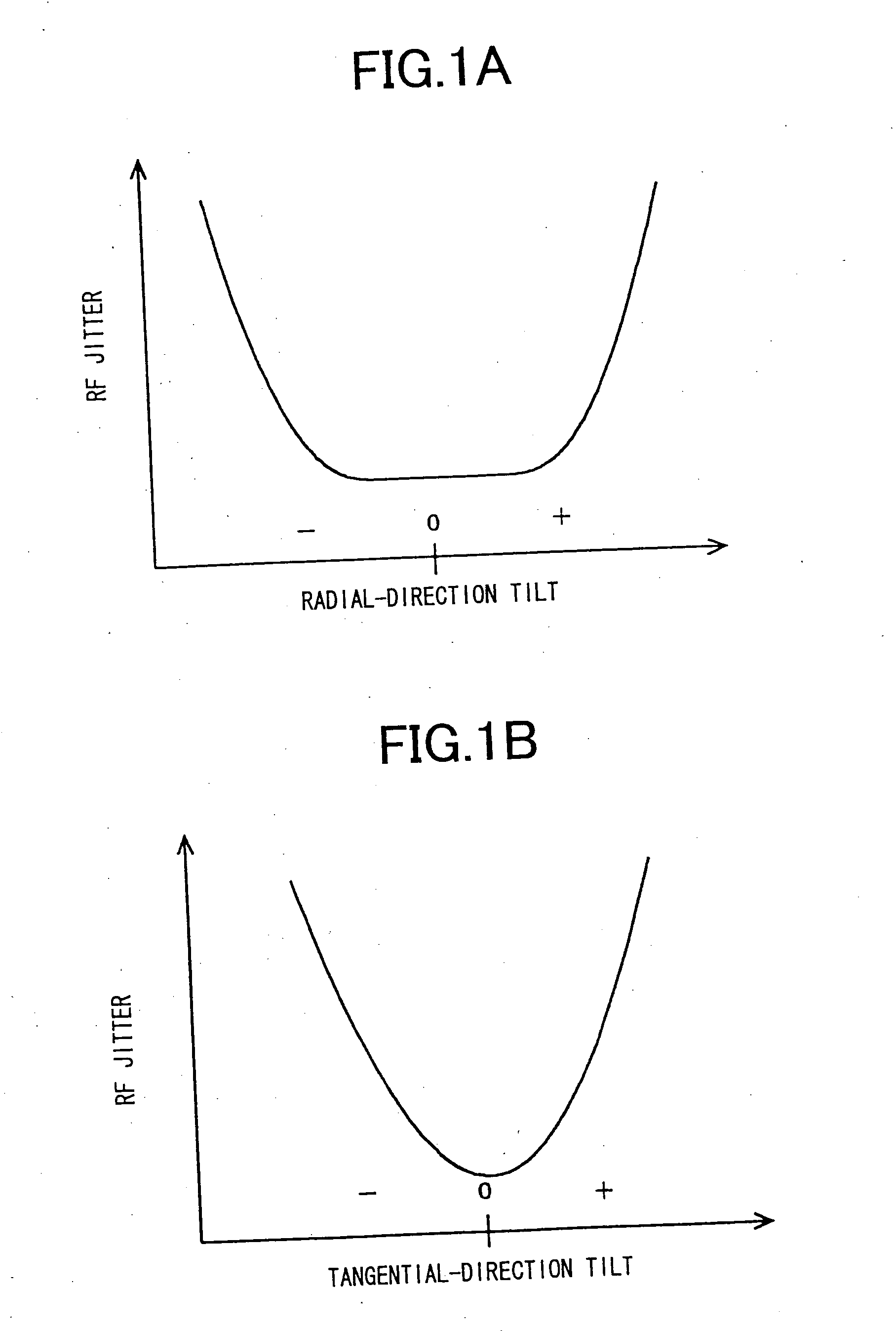
[0084] As a result of the reproduction condition being thus made severe, change in amplitude / jitter amount with respect to the tilt becomes steep, and, thereby, the appropriate tilt adjustment can be...


PUM


Abstract

A tilt detection system includes an optical disk having a series of data recorded therein, the series of data having a pulse width smaller than the minimum pulse width of data recorded in an ordinary optical disk; a reproducing part reproducing a signal from the optical disk by emitting a light beam onto the optical disk; and a tilt detecting part detecting a tilt of the light beam with respect to the optical disk based on a reproduced RF signal provided by the reproducing-part when the series of data having the smaller pulse width is reproduced.

Description

BACKGROUND OF THE INVENTION [0001] 1. Field of the Invention [0002] The present invention relates to tilt detection system, tilt detection method and tilt adjustment method in an optical disk drive for detecting / adjusting a tilt of a light beam with respect to a disk recording surface. [0003] 2. Description of the Related Art [0004] A light beam emitted from a semiconductor laser is incident on a recording surface of an optical disk at right angles through an objective lens for reading a signal recorded on the optical disk. However, when the light beam is not incident on the recording surface of the optical disk at right angles due to inclination of the optical disk and / or inclination of the objective lens, coma aberration is generated. As the coma aberration increases, the cross talk increases, and the S / N ratio of the read signal is degraded. Thereby, distortion occurs in the reproduced waveform, and jitter occurs, as is well known. [0005] Therefore, in order to adjust the tilt of...

Claims


Application Information

Patent Timeline
IPC IPC(8): G11B7/00G11B7/095G11B7/007G11B7/08
CPCG11B7/00736G11B7/0938G11B7/24085G11B7/0956G11B7/0945
Inventor MASHIMO, AKIRAUENO, KEISHI
Owner TEAC CORP
Why Eureka
Try Eureka