Vacuum pump and semiconductor manufacturing apparatus

a vacuum pump and semiconductor manufacturing technology, applied in the field of vacuum pumps, can solve problems such as difficult rotation stability, and achieve the effects of high exhaust performance, stable operation, and high reliability and durability

Inactive Publication Date: 2005-02-03
EBARA CORP
View PDF15 Cites 34 Cited by
  • Summary
  • Abstract
  • Description
  • Claims
  • Application Information

AI Technical Summary

Benefits of technology

[0037] The present invention can provide a compact vacuum pump with high exhaust performance capable of evacuating in pressure ranges from atmospheric pressure to a high vacuum. The i

Problems solved by technology

A magnetic bearing has a support rigidity significantly lower compared to a rolling bearing such as ball bearing, and is therefore likely to be affected by mass imbalance of the

Method used


Image

  • Vacuum pump and semiconductor manufacturing apparatus
  • Vacuum pump and semiconductor manufacturing apparatus
  • Vacuum pump and semiconductor manufacturing apparatus

Examples


first embodiment

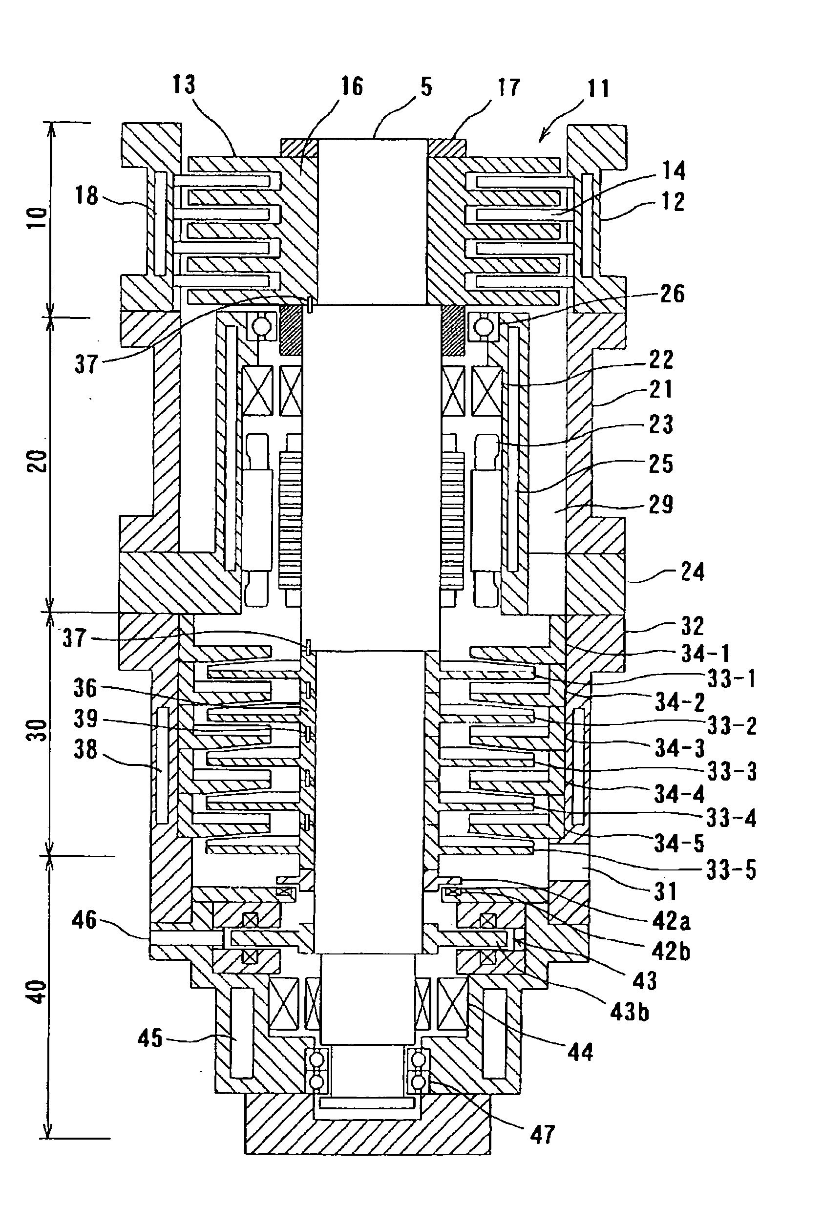
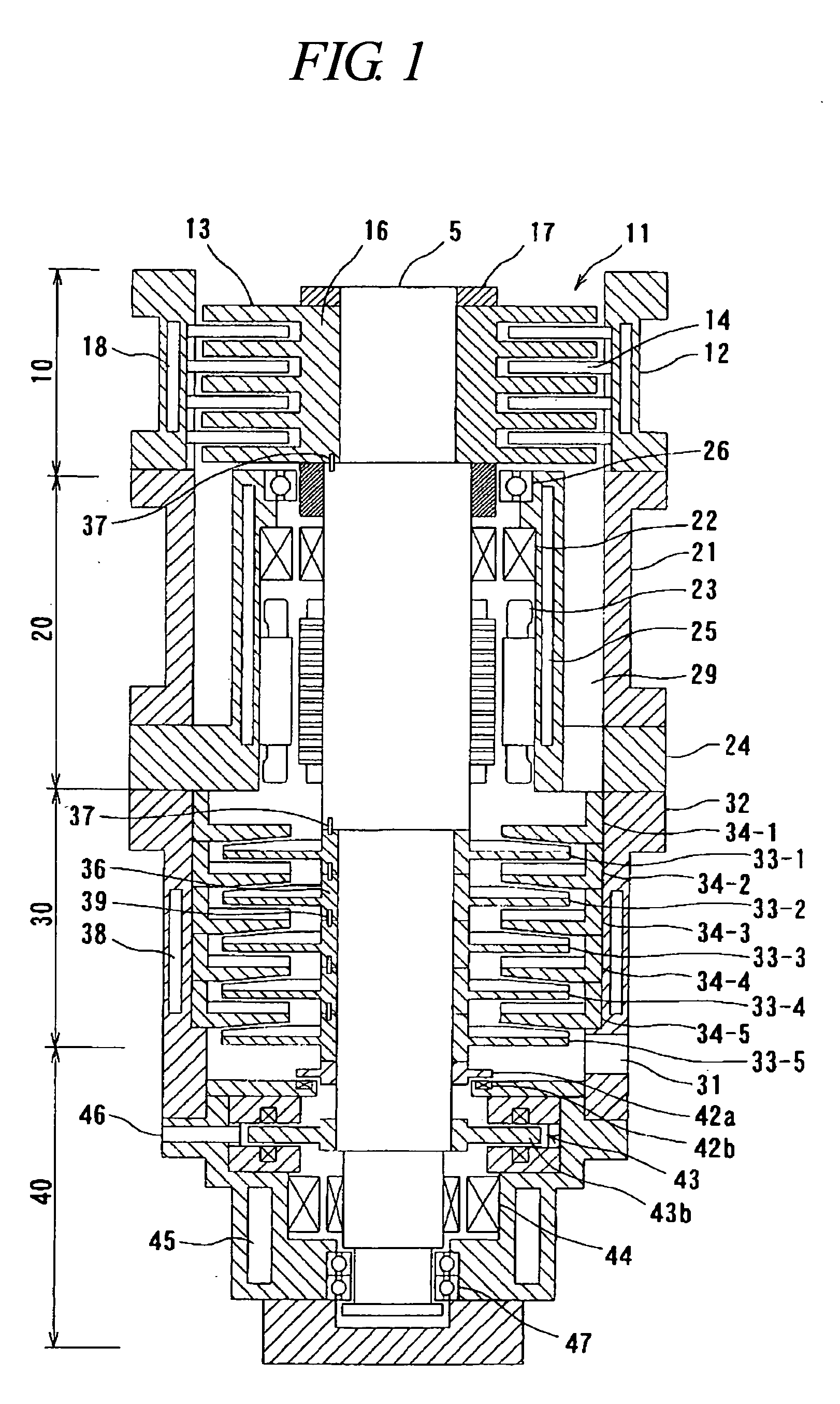
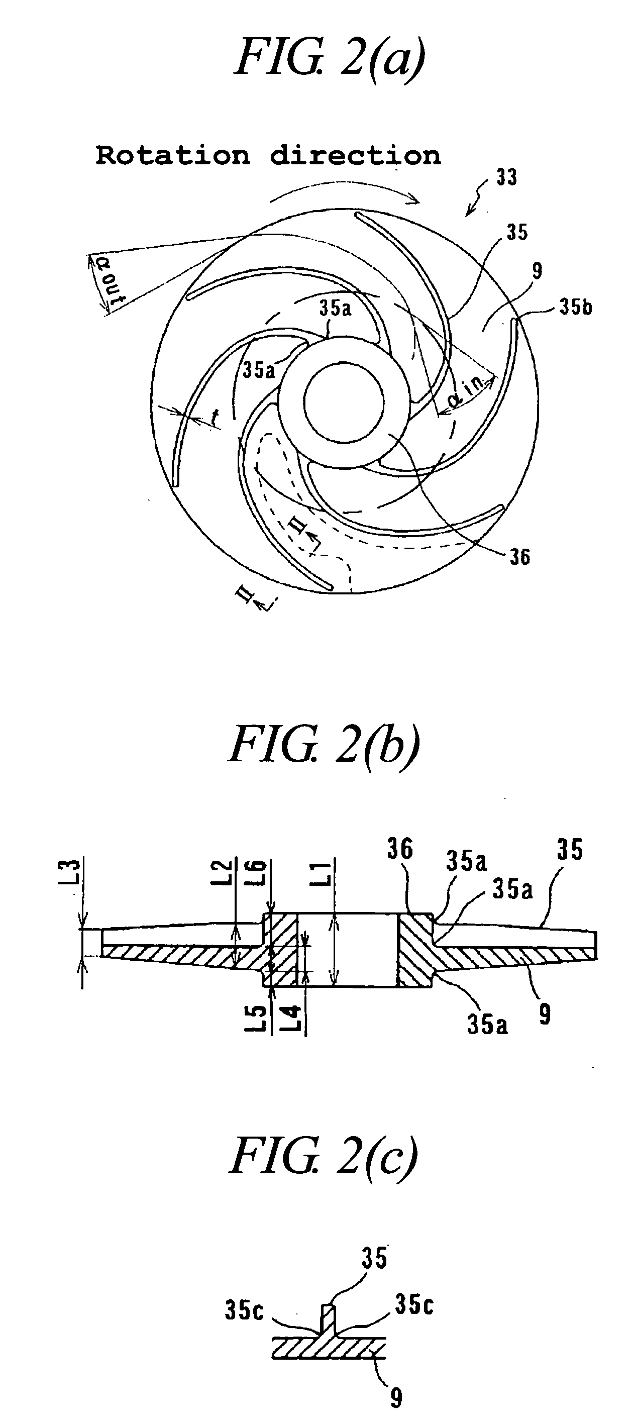
[0082] Some embodiments of the present invention are described below with reference to the drawings. FIG. 1 is a sectional view of a vacuum pump according to the present invention. The upper and lower directions used in the following description with respect to the vacuum pump and a part thereof means the upper and lower directions, respectively, shown in FIG. 1 and similar or corresponding drawings. FIG. 2(a) is a plan view of a centrifugal drag vane shown in FIG. 1, FIG. 2(b) is a sectional view of the centrifugal drag vane shown in FIG. 2(a), and FIG. 2(c) is a sectional view taken along the line II-II shown in FIG. 2(a).

[0083] As shown in FIG. 1, the vacuum pump comprises a turbo molecular pump element 10 as a first exhaust section, an upper housing unit 20 housing an upper radial magnetic bearing 22 as a first bearing, a centrifugal drag pump element 30 as a second exhaust section, and a lower housing unit 40 housing a lower radial magnetic bearing 44 as a second bearing and an...

sixth embodiment

[0168]FIG. 17 is a sectional view of a vacuum pump according to the present invention. As shown in FIG. 17, a purge gas introduced from the upper purge gas port 73 passes through the purge gas flow passage 74 formed in the upper housing 24, and through the upstream side of the upper radial magnetic bearing 22 and the downstream side of the motor 23 to the inside of the upper housing 24. This leaves the upper radial magnetic bearing 22 and the motor 23 with a purge gas atmosphere, preventing a corrosive process gas to be exhausted from entering the upper housing 24. The communication portion between the upper housing 24 and the centrifugal drag pump element 30 is provided with a labyrinth seal mechanism 75, which can protect the inside of the upper housing 71 from the gas to be exhausted. Therefore, components of the upper radial magnetic bearing 22 and the motor 23 can be prevented from being corroded, and deposits can be prevented from accumulating on the above components.

[0169] Si...

seventh embodiment

[0170]FIG. 18 is a sectional view of a vacuum pump according to the present invention. The vacuum pump according to the present embodiment is suitably used to exhaust a corrosive process gas. As shown in FIG. 18, in the vacuum pump of the present embodiment, the inner surface of a stator 22a of the upper radial magnetic bearing 22 and the inner surface of a motor stator 23a of the motor 23 are covered with a protective member 27, while the outer surface of a rotor 22b of the upper radial magnetic bearing 22 and the outer surface of a motor rotor 23b of the motor 23 are coated with a protective member 28. In the same manner, both a stator 44a and a rotor 44b of the lower radial magnetic bearing 44 are provided with protective members 48 and 49, respectively.

[0171] In an axial magnetic bearing, in general, the magnetic field in the magnetic circuit of the electromagnet is not affected by rotation of the rotor. Therefore, it is not necessary to make an effort to reduce an eddy-current ...


PUM


Abstract

To provide a vacuum pump capable of evacuating in pressure ranges from an atmospheric pressure to a high vacuum, capable of rotating at a high speed to be downsized and improved in pumping performance, and capable of producing a completely oil-free vacuum.
A vacuum pump for exhausting a gas comprises: a main shaft 5 rotatably supported by a bearing 22; a motor 23 for driving the main shaft 5 for rotation; a first exhaust section 10 having a first rotary vane 13 attached to the main shaft 5, a first fixed vane 14 fixed in a first casing 12, and an intake port 11; and a second exhaust section 30 having a second rotary vane 33 attached to the main shaft 5, a second fixed vane 34 fixed in a second casing 32, and an exhaust port 31. The intake port 11 is located in the vicinity of an end of the main shaft 5, and the first exhaust section 10, the bearing 22 and the second exhaust section 30 are arranged in this order axially along the main shaft 5.

Description

BACKGROUND OF THE INVENTION [0001] 1. Field of the Invention [0002] The present invention relates to a vacuum pump, and more particularly to a vacuum pump capable of effective evacuation in pressure ranges from an atmospheric pressure to a high vacuum. [0003] 2. Description of the Related Art [0004]FIG. 31 is a schematic diagram of a semiconductor manufacturing apparatus with a conventional vacuum pump. [0005] As shown in FIG. 31, a semiconductor manufacturing apparatus 101 has a plurality of process chambers 102, a transfer chamber 103 and a cassette chamber 104. A wafer (substrate) to be processed is placed in the cassette chamber 104, transferred by way of the transfer chamber 103 to the process chamber 102, where it is subject to a predetermined process (such as PVD, CVD, and etching). A plurality of process chambers 102 are commonly provided in order to perform a plurality of processes or to increase the number of wafers to be processed in the single semiconductor manufacturing...

Claims


Application Information

Patent Timeline
IPC IPC(8): F04D29/056F04D17/16F04D19/04F04D29/058
CPCF04D17/168F04D19/046F04D23/008F04D29/266F04D29/30F04D29/058F04D29/644F04D29/662
Inventor SEKIGUCHI, SHINICHIMIYAMOTO, MATSUTARO
Owner EBARA CORP
Why Eureka
Try Eureka