Thermal treating apparatus

Inactive Publication Date: 2005-02-10
TOKYO ELECTRON LTD
View PDF7 Cites 14 Cited by
  • Summary
  • Abstract
  • Description
  • Claims
  • Application Information

AI Technical Summary

Benefits of technology

[0020] An object of the present invention is to provide a thermal processing unit suitable for rapid heating a

Problems solved by technology

However, in the conventional thermal processing unit, since the reaction container has the double-tube structure, the thermal capacity thereof is large.
Thus, the conventional thermal processing unit

Method used


Image

  • Thermal treating apparatus
  • Thermal treating apparatus
  • Thermal treating apparatus

Examples


example

[0095] Hereinafter, a specific example of the invention is explained.

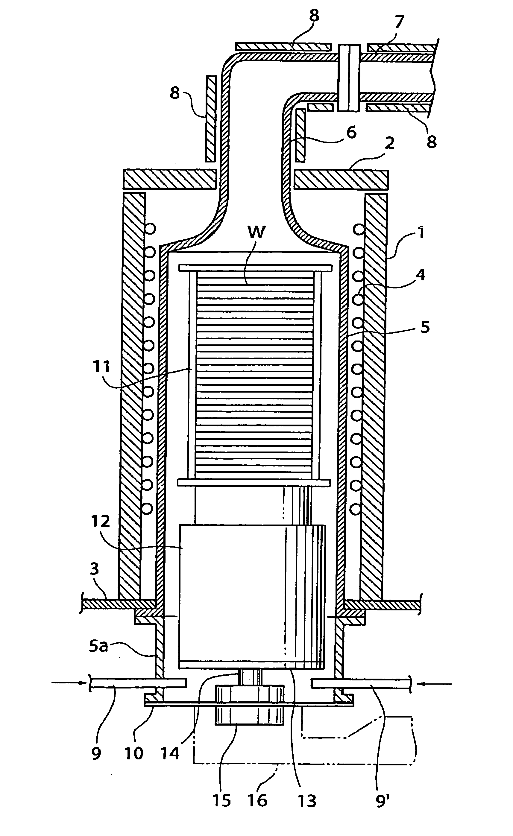
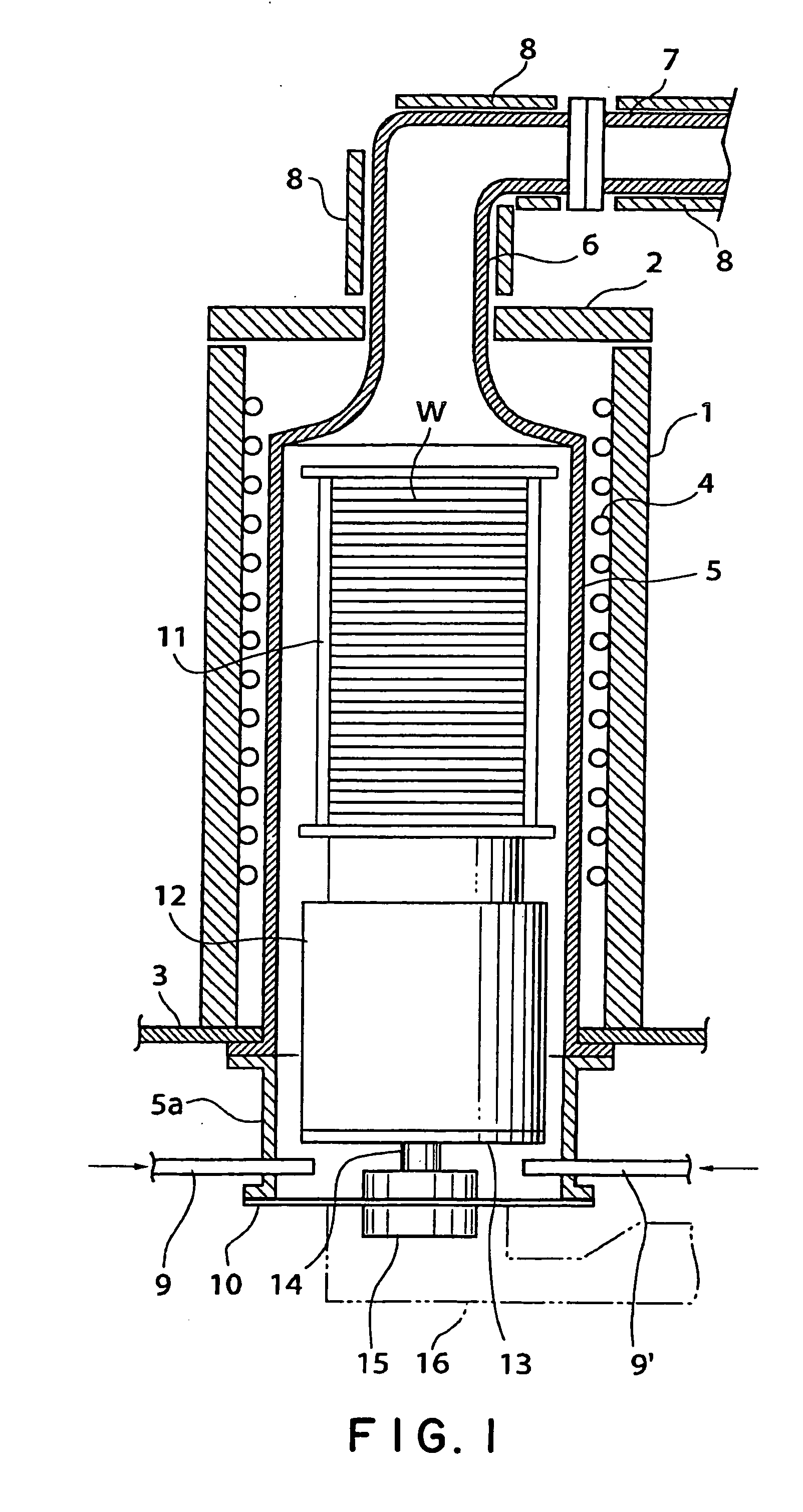
[0096] A process tube as shown in FIG. 1 was made of quartz glass.

[0097] 100 silicon wafers were mounted on a wafer boat made of quartz glass in an alignment, and a silicon nitride film having a thickness of 70 nm was deposited on a surface of each silicon wafer at a reaction temperature of 700° C. by using the process tube and by using a silane-base gas as a reaction gas and an ammonium gas. The gas-discharging-pipe connecting portion 6 was heated to 700° C. by means of a carbon wire heater.

[0098] As a comparison, a silicon nitride film was formed under the same conditions, by using a double-tube type of process tube as shown in FIG. 4.

[0099] As a result, in the example of the invention, it took 200 minutes to complete the steps of from preliminary heating to taking-out the silicon wafers. On the other hand, according to the comparison, it took 230 minutes.

[0100] In addition, in both cases, particle contamina...


PUM

PropertyMeasurementUnit
Temperatureaaaaaaaaaa
Angleaaaaaaaaaa
Temperatureaaaaaaaaaa

Abstract

The present invention is a thermal processing unit including: a heating-furnace body whose upper end has an opening; a heating unit provided on an inside wall of the heating-furnace body; a reaction container consisting of a single tube contained in the heating-furnace body; a gas-discharging-pipe connecting portion formed at an upper portion of the reaction container; and a first temperature controlling unit provided around the gas-discharging-pipe connecting portion.

Description

FIELD OF THE INVENTION [0001] The present invention relates to a thermal processing unit and a thermal processing method which are suitable for a thermal process to an object to be processed such as a semiconductor wafer. DESCRIPTION OF THE RELATED ART [0002] Conventionally, in a semiconductor manufacturing process, there is a step of depositing a thin film or an oxide film onto a surface of a semiconductor wafer as an object to be processed, or a step of conducting a diffusion of impurities onto the surface. For these steps, a thermal processing unit such as a CVD unit, an oxide-film forming unit or a diffusion unit has been used. [0003] In such a thermal processing unit, a plurality of wafers, which are objects to be processed, are placed on a holding tool called a wafer boat in a vertical arrangement, and then loaded in a reaction container called a process tube that has been heated to a high temperature. Then, a reaction gas is introduced into the reaction container, so that a t...

Claims


Application Information

Patent Timeline
IPC IPC(8): C23C16/44C23C16/455H01L21/00H01L21/205H01L21/22
CPCH01L21/67109H01L21/67098H01L21/205
Inventor SAITO, TAKANORIMAKIYA, TOSHIYUKIOSANAI, HISAEITAKIZAWA, TSUYOSHISHIMAZU, TOMOHISAHASEBE, KAZUHIDEYAMAMOTO, HIROYUKISAITO, YUKIMASAYAMAGA, KENICHI
Owner TOKYO ELECTRON LTD
Why Eureka
Try Eureka