Hydraulic engine valve actuator

a technology for hydraulic engine valves and actuators, which is applied in the direction of machines/engines, non-mechanical valves, valve arrangements, etc., can solve the problems of increasing the complexity affecting the service life of the valve actuator, etc., and reducing the cost of changes required in the design and manufacture of the manifold

Inactive Publication Date: 2005-02-10
GM GLOBAL TECH OPERATIONS LLC
View PDF4 Cites 9 Cited by
  • Summary
  • Abstract
  • Description
  • Claims
  • Application Information

AI Technical Summary

Benefits of technology

[0009] In operation, oil is directed to the oil distributor valves, which sequentially distribute pressure oil to the associated valve actuators from the supply manifold. Pressure oil distributed to each valve actuator forces the respective boost piston and the drive piston axially downward in the housing and partially opens the associated engine valve. Part way through the piston stroke, the boost piston engages a stop, while the drive piston continues to move axially downward for a greater distance. The continued motion of the drive piston completes opening of the engine valve. Subsequently, the oil distributor valve reduces the oil pressure in the housing and a valve spring returns the valve to its closed position, thereby moving the drive piston and boost piston back to their original positions against the liner.

Problems solved by technology

Mounting of the hydraulic cylinder and pistons and the position sensor in the manifold increases its complexity and complicates assembly, disassembly and serviceability of the assembly.
Modification of the hydraulic components is also complicated by the expense of changes required in design and manufacture of the manifold.

Method used


Image

  • Hydraulic engine valve actuator
  • Hydraulic engine valve actuator
  • Hydraulic engine valve actuator

Examples


Embodiment Construction

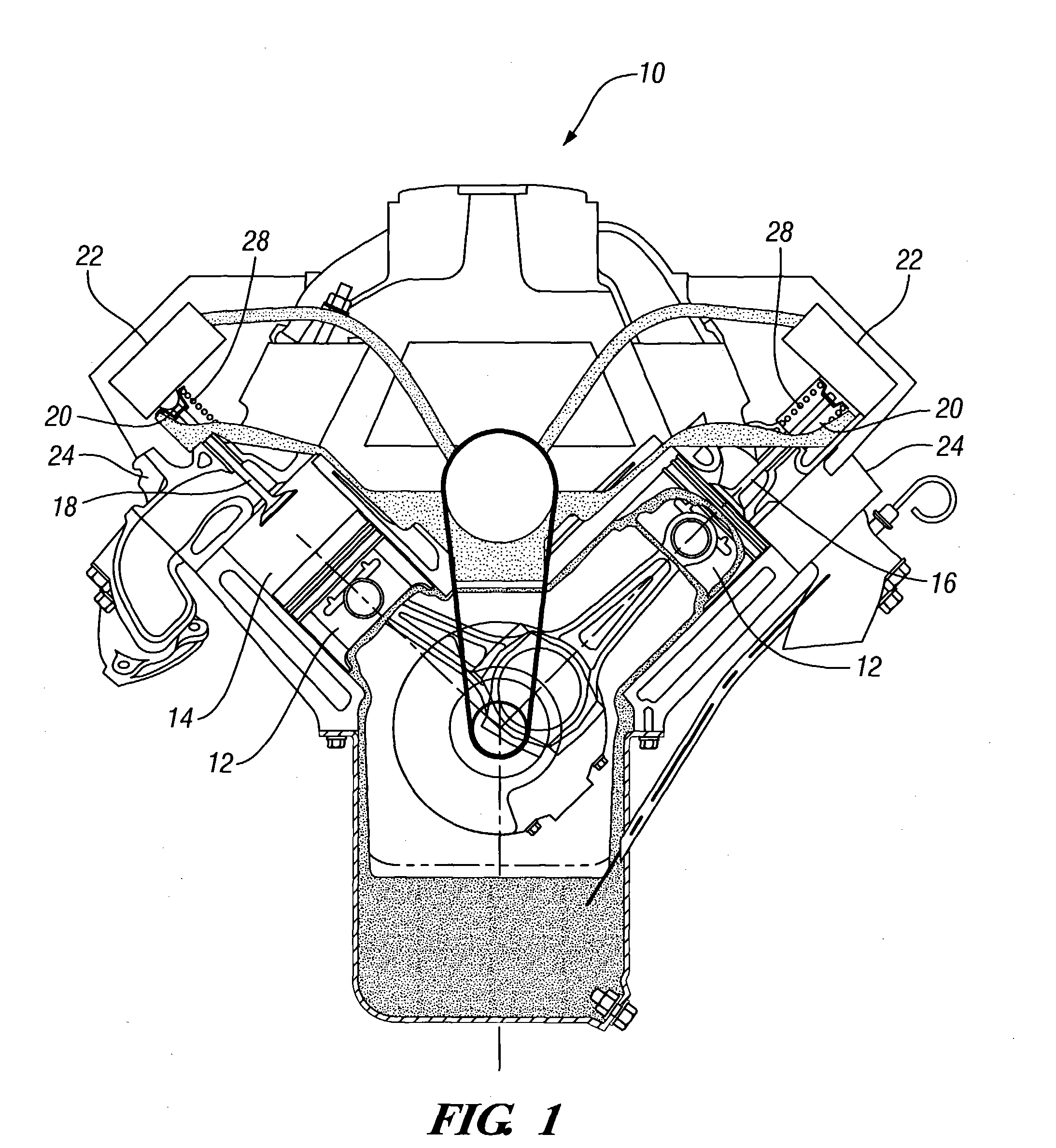
[0016] Referring now to FIG. 1 of the drawings in detail, numeral 10 generally indicates a camless internal combustion engine. Engine 10 has a plurality of pistons 12, reciprocable within engine cylinders 14. Each cylinder 14 has associated intake and exhaust valves 16, 18. The valves 16, 18 are hydraulically actuated by valve actuators 20 (FIG. 2) fixed to hydraulic supply manifolds 22 mounted on cylinder heads 24 and closing upper ends of the cylinders 14. The actuators 20 are controlled by oil distributor valves 26 (FIGS. 3,4) which are activated by a controller 27 to deliver pressure oil to or cut off pressure oil from the valve actuators 20. Specifically, the valves 16, 18 are opened by hydraulic actuator pistons, not shown, and are closed by valve springs 28 conventionally mounted on the cylinder heads 24.

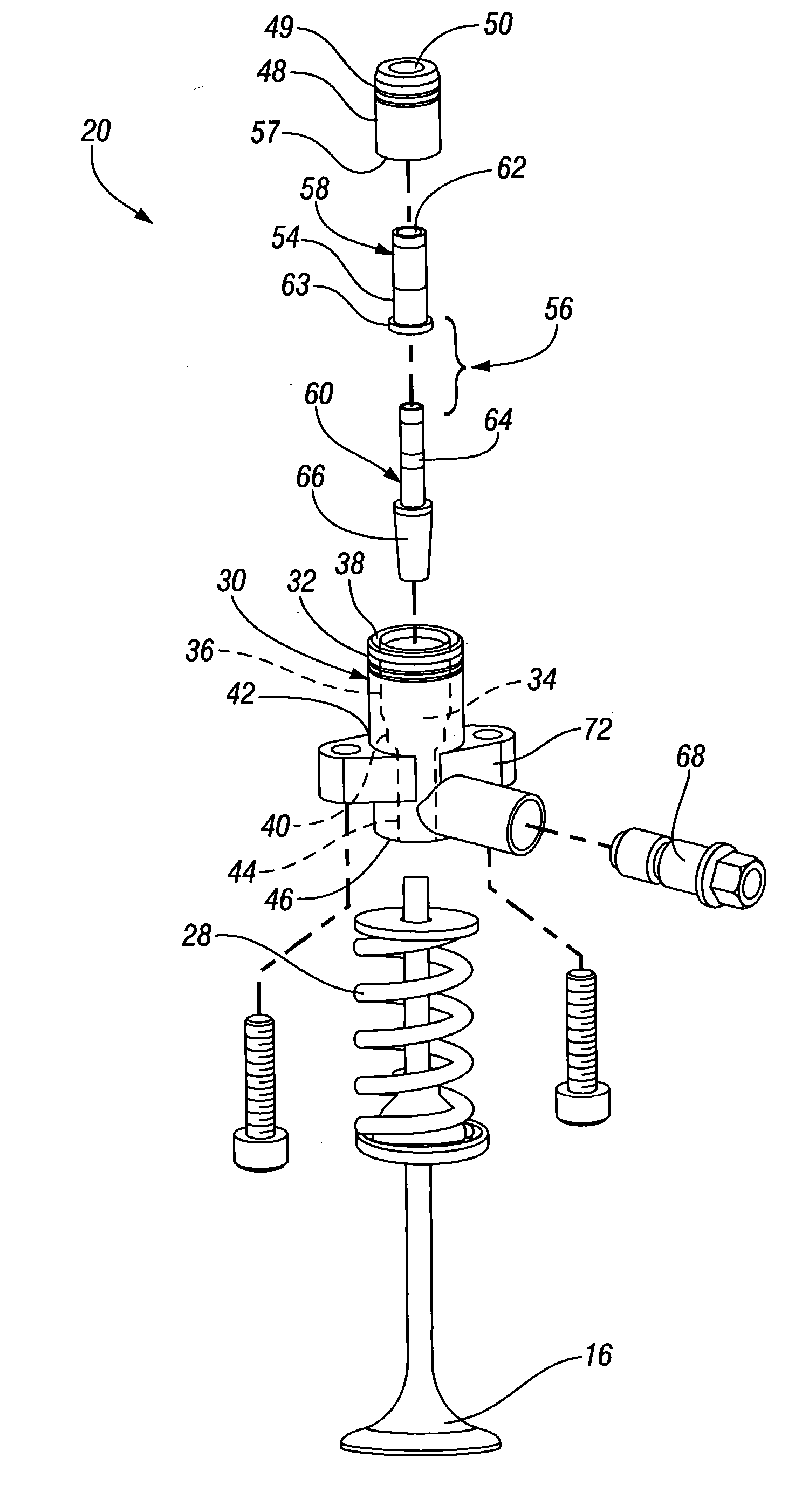
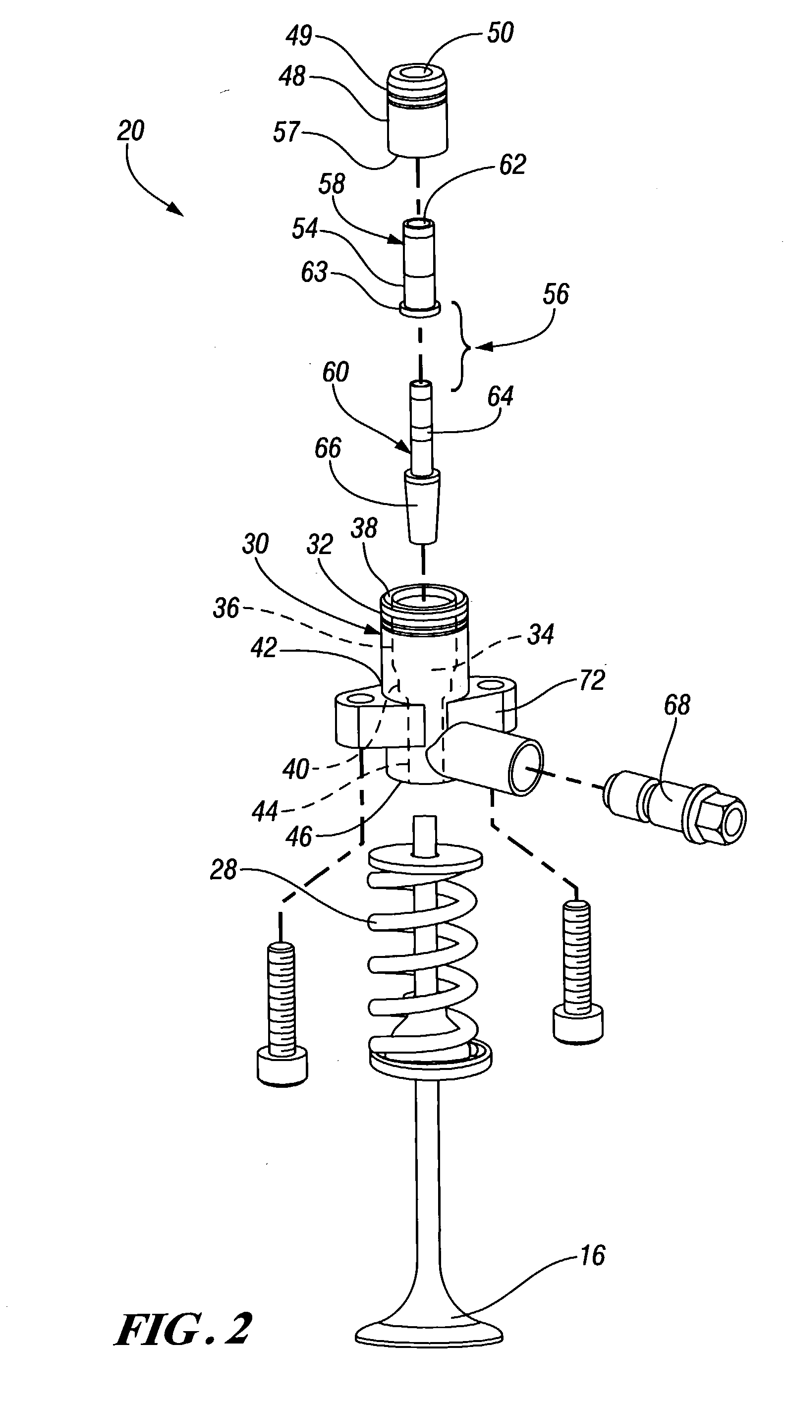
[0017] In accordance with the present invention, the valve actuators 20 comprise integral assemblies, as shown in FIG. 2. Each actuator 20 includes a cylindrical housing 30 ...


PUM


Abstract

An integrated hydraulic valve actuator for use in a camless internal combustion engine. The valve actuator includes a separate bolt-on housing defining a through opening receiving a cylindrical liner. The liner internally defines an internal cylinder providing a riding surface, which coaxially surrounds an outer surface of a tubular boost piston. The boost piston defines an inner cylinder, which provides a riding surface for a drive piston fitted within the inner cylinder of the boost piston. The pistons are axially reciprocable within the liner cylinder. A piston position sensor extends radially into the housing and engages a cam on the drive piston to relay the position of the drive piston to a controller. The actuator is preassembled and the housing is attached to an engine cylinder head or cylinder head supply manifold to operate an associated exhaust or intake valve.

Description

TECHNICAL FIELD [0001] This invention relates to engine valve actuating apparatus and more particularly to a hydraulic engine valve actuator integrated in a separate housing assembly. BACKGROUND OF THE INVENTION [0002] Piston type internal combustion engines generally utilize mechanically driven camshafts and valve gear for operation of intake and exhaust valves. Electric and hydraulic valve actuators have also been proposed in order to provide improved control of valve actuation and timing. [0003] A hydraulic valve system may comprise a hydraulic pump, a controller, a hydraulic fluid manifold, and one or more pistons reciprocable in a hydraulic cylinder provided in the hydraulic fluid manifold. The manifold delivers hydraulic fluid to the hydraulic cylinder to reciprocate the pistons and actuate an associated intake or exhaust valve. A position sensor may also be mounted to the manifold to feed back the valve position to the controller. [0004] Mounting of the hydraulic cylinder and...

Claims


Application Information

Patent Timeline
Patent Type & Authority Applications(United States)
IPC IPC(8): F01L9/10F01L1/34F01L1/46
CPCF01L2800/17F01L9/02F01L9/10
Inventor LIEDTKE, JENNIFER L.WENZEL, THOMAS E.
Owner GM GLOBAL TECH OPERATIONS LLC
Why Eureka
Try Eureka