Plasma display panel having igniter electrodes

a technology of plasma display panel and igniter electrode, which is applied in the direction of gas discharge electrode, sustain/scan electrode, gas discharge tube, etc., can solve the problems of poor energy transformation efficiency of pdp at the respective steps, weak discharge, and inability to address discharge, etc., to achieve stable driving and low discharge voltage

Inactive Publication Date: 2005-02-10
SAMSUNG SDI CO LTD
View PDF9 Cites 10 Cited by
  • Summary
  • Abstract
  • Description
  • Claims
  • Application Information

AI Technical Summary

Benefits of technology

[0016] It may be an aspect of the present invention to provide a PDP in which a separate subsidiary electrode may be provided within the discharge cell to permit plasma discharge with a lower discharge voltage and to stabilize driving.

Problems solved by technology

Thus the discharge may weaken, and the address discharge may dissipate.
The energy transformation efficiency of the PDP at the respective steps may be not good, and hence, the efficiency of the currently available PDP (the ratio of brightness to power consumption) may be lower than the CRT.
For example, the PDP involves disadvantages of high power consumption and significant heat generation.
However, with such techniques, the discharge voltage may be not sufficiently reduced, and hence, the problem of high power consumption may be not yet solved.

Method used


Image

  • Plasma display panel having igniter electrodes
  • Plasma display panel having igniter electrodes
  • Plasma display panel having igniter electrodes

Examples


first embodiment

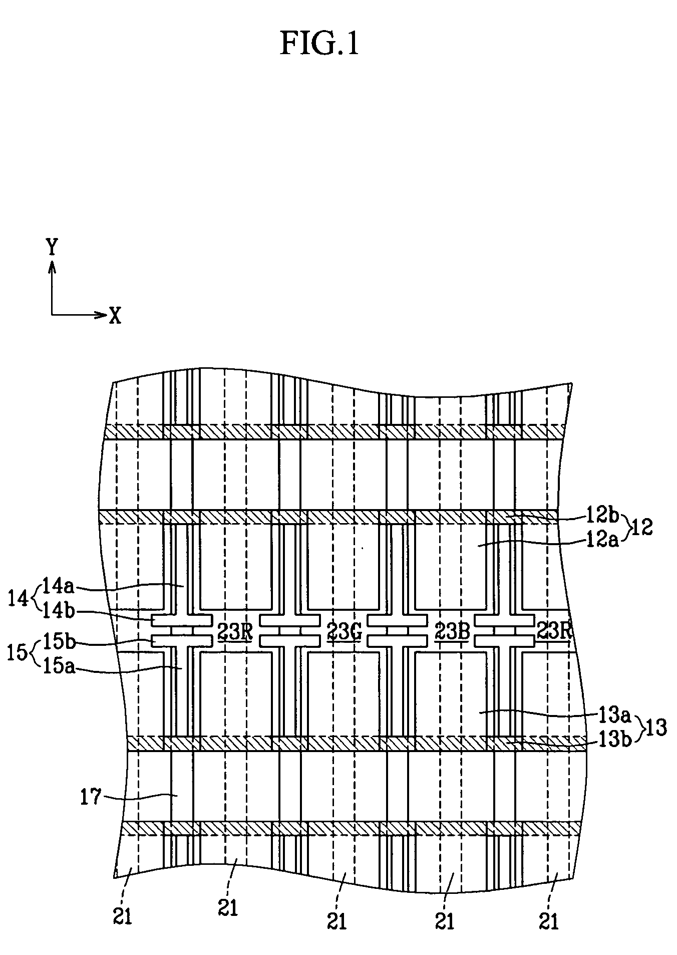
[0047]FIG. 1 is a plan view of a PDP according to the present invention.

[0048] A plasma display panel (PDP) according to the first embodiment may include a first substrate (not shown) and a second substrate (not shown) provided substantially in parallel with a predetermined gap therebetween. A plurality of discharge cells 23R, 23G, and 23B in which plasma discharge may take place may be defined by barrier ribs 17 between first substrate and second substrate. Discharge sustain electrodes 12 and 13 may be formed along one direction (x-axis direction of the drawings) on first substrate, and address electrodes may be formed in a direction intersecting the discharge electrode (y-axis direction of the drawings) on second substrate.

[0049] The barrier ribs 17 may be arranged between the neighboring address electrodes 21 and may be parallel to the address electrodes 21. Alternatively, a closed barrier rib structure with a barrier rib member that may be parallel to the address electrode 21 a...

second embodiment

[0062]FIG. 4 is a partial plan view of a PDP according to the present invention.

[0063] As shown in FIG. 4, an igniter electrode 25 may extend from the bus electrode 13b selected from the pair of bus electrodes 12b and 13b facing each other, and protruded toward the inside of the respective discharge cells 23R, 23G, and 23B. For example, the igniter electrode 25 may have an extension 25a extending from the bus electrode 13b along the barrier rib 17 that may be parallel to the address electrode 21 while being placed over the barrier rib 17, and a protrusion 25b branched from the end of the extension 25a, and protruded toward the inside of the discharge cells 23R, 23G, and 23B. The bus electrode 13b connected to the igniter electrode 25 may function as a scan electrode or a sustain electrode.

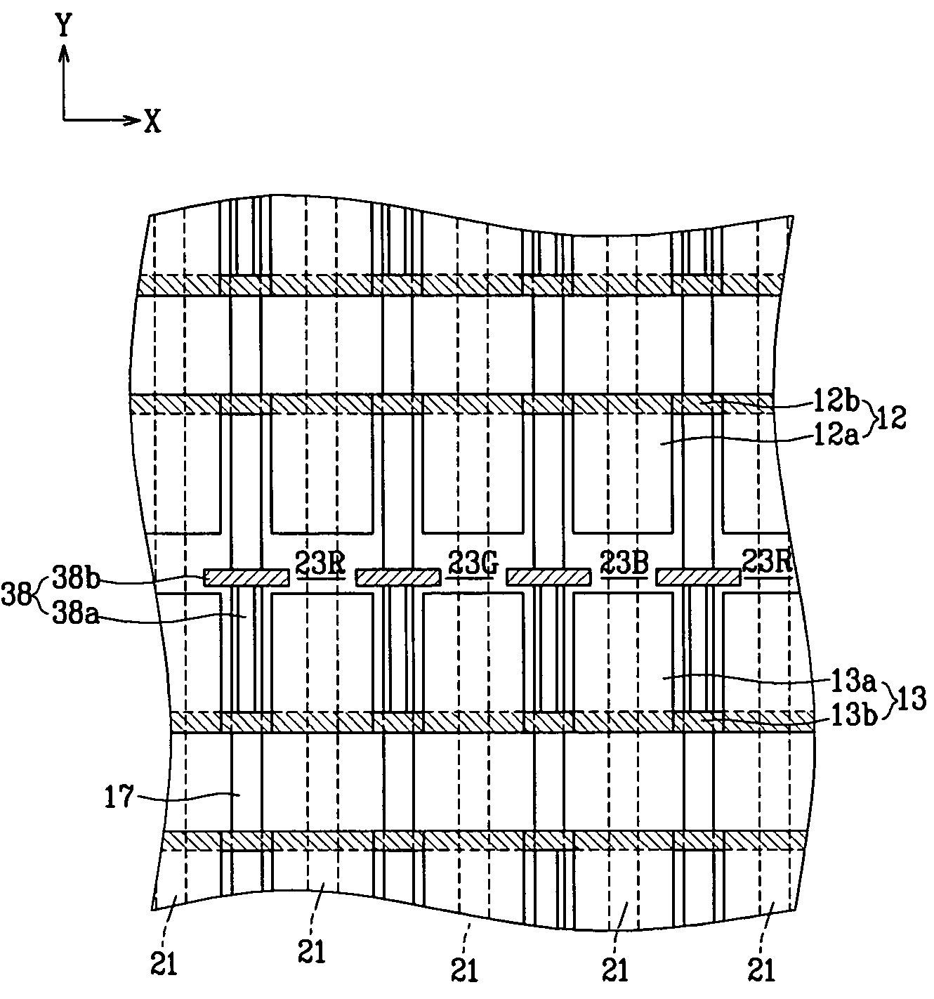
[0064]FIG. 5 is a partial plan view of a modified example of PDP of FIG. 4.

[0065] Igniter electrode 38 according to this modified example of PDP may have extension 38a that may have higher resist...

third embodiment

[0066]FIG. 6 is a partial plan view of a PDP according to the present invention.

[0067] As shown in FIG. 6, igniter electrodes 27 and 28 may be alternately connected to a pair of bus electrodes 12b and 13b facing each other. For example, the igniter electrodes 27 and 28 may be periodically arranged per two barrier ribs 17 for forming the discharge cells 23R, 23G, and 23B, not per the respective barrier ribs 17. The igniter electrodes 27 and 28 connected to the bus electrodes 12b and 13b facing each other may not face each other, but may be deviated from each other. The igniter electrodes 27 and 28 may have extensions 27a and 28a extending from the respective bus electrodes 12b and 13b along the barrier ribs 17 that may be parallel to the address electrodes 21 while being placed over the barrier ribs 17, and protrusions 27b and 28b branched from the ends of the extensions 27a and 28a, and protruded toward the inside of the discharge cells 23R, 23G, and 23B.

[0068]FIG. 7 is a partial p...


PUM


Abstract

A plasma display panel, and particularly to a surface-discharge plasma display panel that may have an electrode structure in which a pair of discharge sustain electrodes may be arranged at respective discharge cells between two substrates to make the display discharge. The plasma display panel may include igniter electrodes formed over barrier ribs extending from discharge sustain electrodes along the barrier ribs, and protruding toward the inside of discharge cells at their ends.

Description

CROSS-REFERENCE TO RELATED APPLICATION [0001] The present application claims the benefit of Korean Patent Application No. 2003-005464 filed Aug. 7, 2003, hereby incorporated fully by reference, and of Korean Patent Application No. 2004-0026982 filed Apr. 20, 2004, hereby also incorporated fully by reference. BACKGROUND OF THE INVENTION [0002] (a) Field of the Invention [0003] The present invention may relate to a plasma display panel, and particularly to a surface-discharge plasma display panel that may have an electrode structure in which a pair of discharge sustain electrodes may be arranged at respective discharge cells between two substrates to make the display discharge. [0004] (b) Description of Related Art [0005] Generally, a plasma display panel (PDP) may be a display device that operates by exciting phosphors using ultraviolet rays radiated from plasma obtained by discharging an electric current through a gas. The desired result may be red (R), green (G), and blue (B) visib...

Claims


Application Information

Patent Timeline
Patent Type & Authority Applications(United States)
IPC IPC(8): H01J17/04H01J17/49
CPCH01J11/12H01J11/28H01J11/24
Inventor KWON, JAE-IKKANG, KYOUNG-DOO
Owner SAMSUNG SDI CO LTD
Why Eureka
Try Eureka