Distributed delay-locked-based clock and data recovery systems

a delay-locked, clock-based technology, applied in pulse generators, pulse manipulation, pulse techniques, etc., can solve the problems of inability to scale to higher speeds and frequencies, vco can introduce undesirable timing jitter, and full-rate architectures

Active Publication Date: 2005-02-10
RGT UNIV OF CALIFORNIA
View PDF13 Cites 27 Cited by
  • Summary
  • Abstract
  • Description
  • Claims
  • Application Information

AI Technical Summary

Benefits of technology

[0007] A clock and data recovery (CDR) system is provided for aligning a local-clock with an incoming data stream. In one exemplary embodiment, the CDR system includes a first section configured to compare the phase of the data stream with the phase of the local clock and output a control voltage corresponding to the difference in phase between the data stream and

Problems solved by technology

However, the use of a VCO can introduce an undesirable amount of timing jitter.
Conventional CDR circuits also commonly use full-rate architectures, which do not allow for easy scaling to higher speeds and frequencies.
This is because full-rate architectures require more system components to work at higher frequencies and this limits the maximum use of the technology capabilities.
Certain half-rate structures also use a large number of current-mode logic (“CML”) logic components to design the phase detector building

Method used


Image

  • Distributed delay-locked-based clock and data recovery systems
  • Distributed delay-locked-based clock and data recovery systems
  • Distributed delay-locked-based clock and data recovery systems

Examples


Embodiment Construction

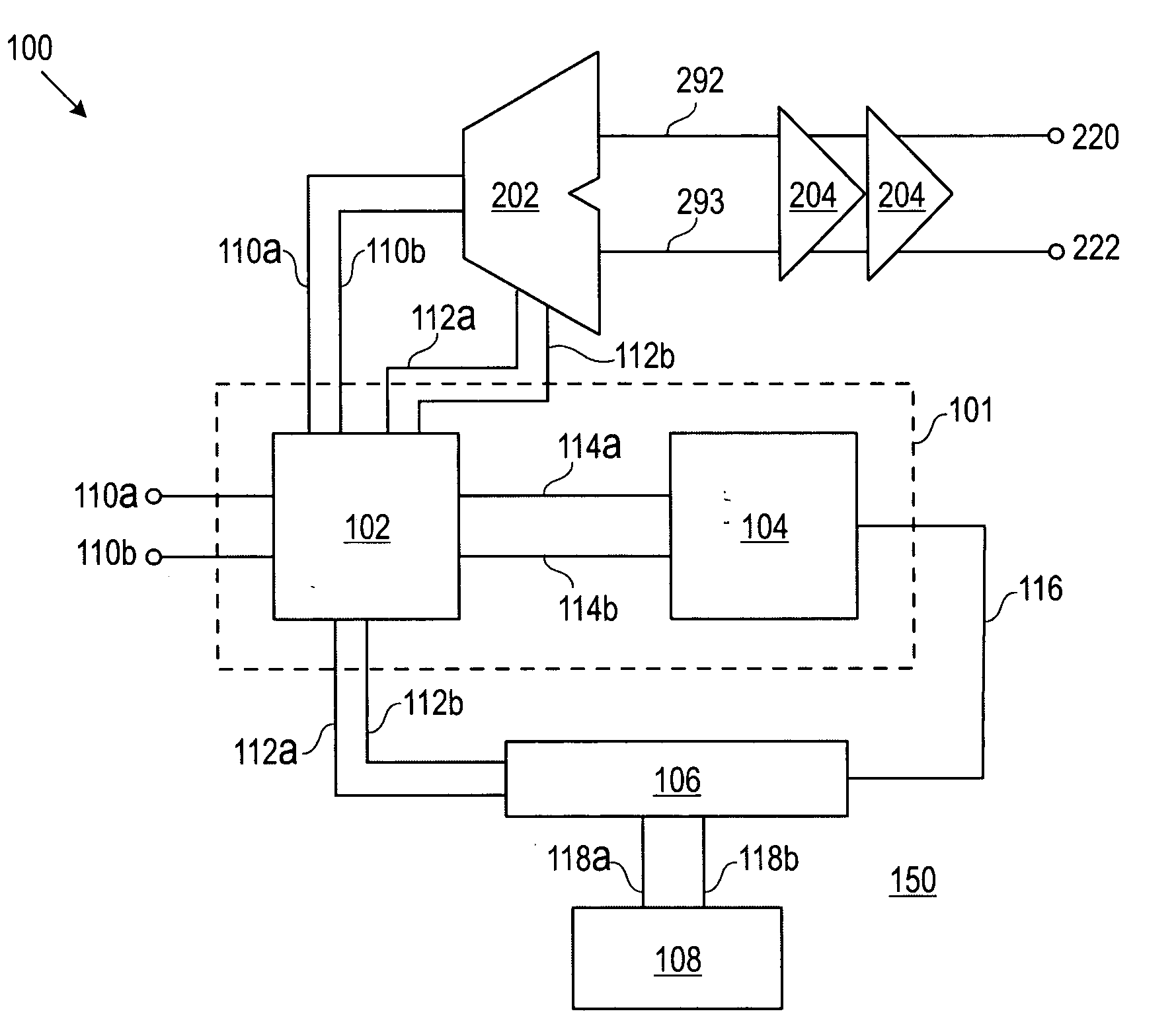
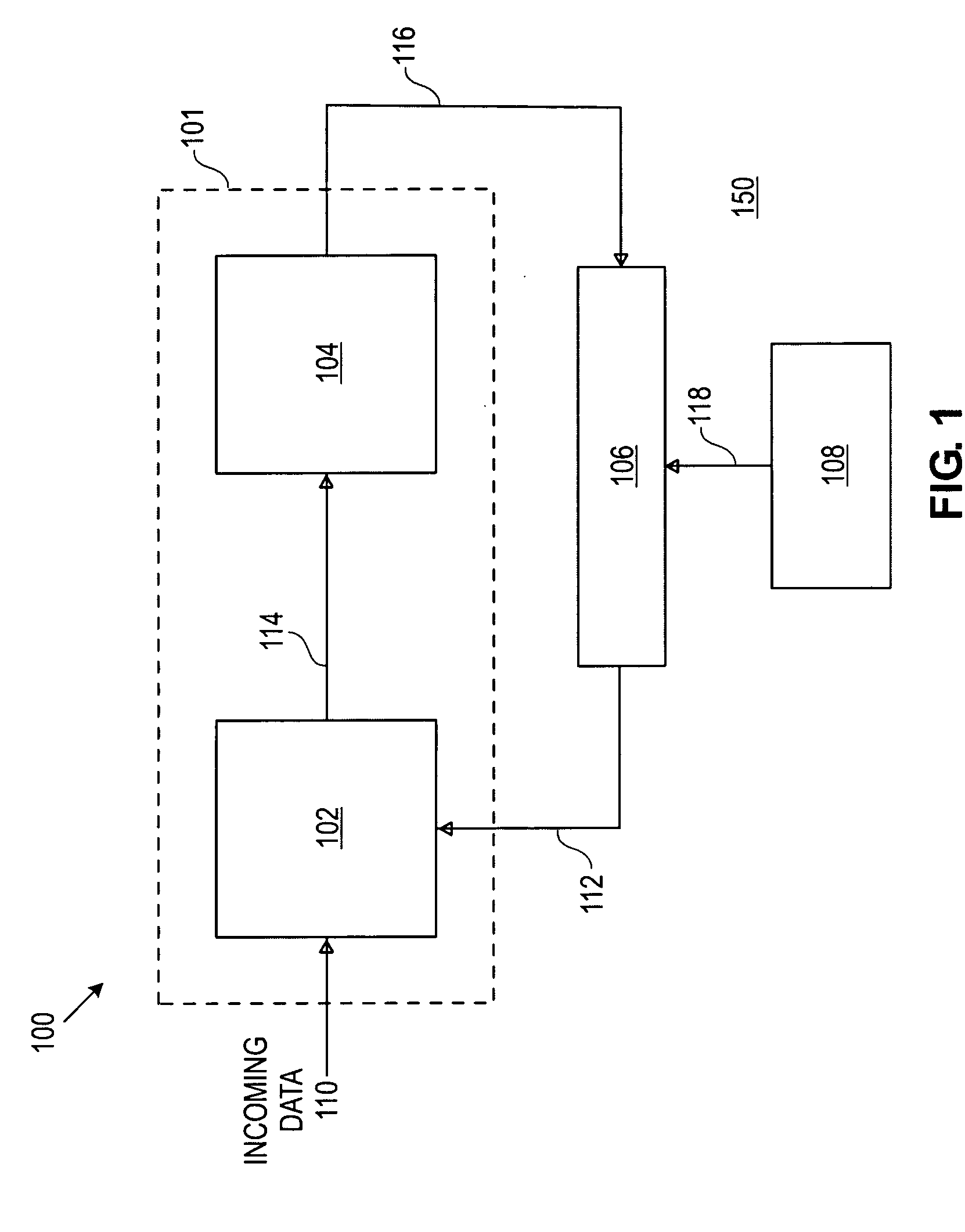
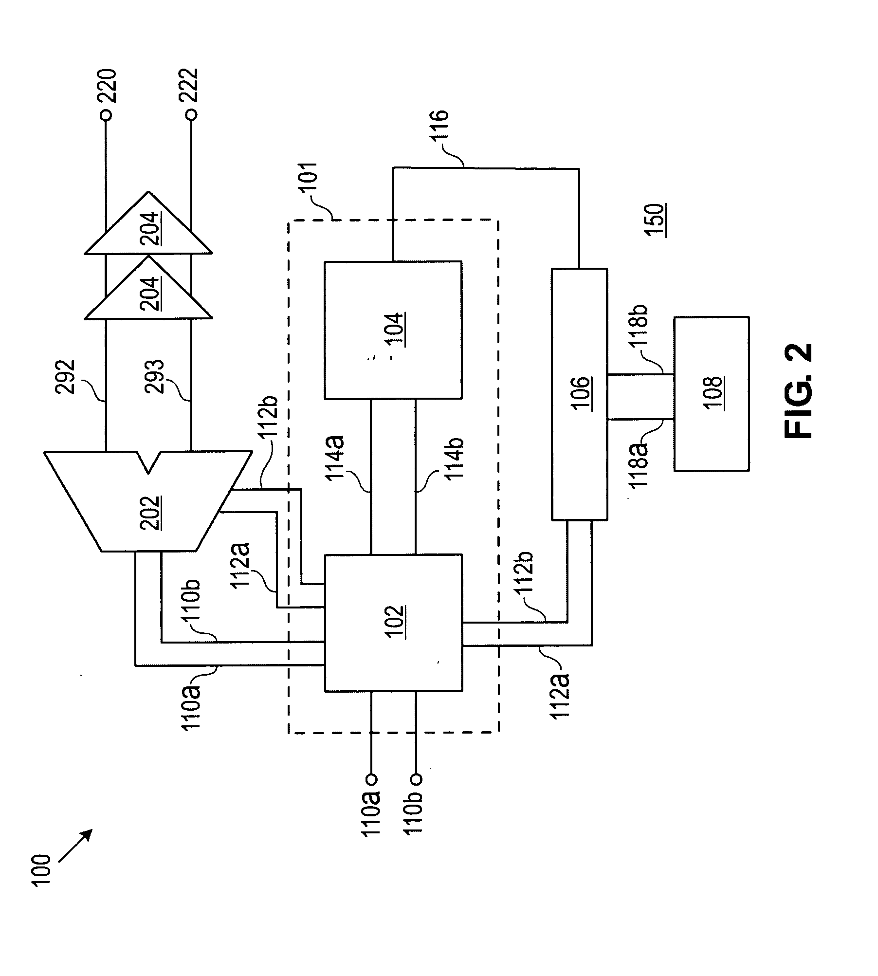
[0024] Distributed clock and data recovery (CDR) systems using a delay-locked architecture with distributed variable delay lines are provided herein. The CDR systems are scalable across a wide range of bit rates and frequencies making them suitable for numerous applications including, but not limited to, broadband high-speed optical communication systems. The CDR systems can be implemented in inexpensive digital semiconductor processes, such as complementary-metal-oxide semiconductor (CMOS) processes and the like.

[0025]FIG. 1 depicts one exemplary embodiment of CDR system 100. CDR system 100 uses variable delay line 106 to vary the delay in a clock signal to “lock” the incoming data through feedback control. In this embodiment, CDR system 100 includes a first section 101 coupled with a variable delay line 106. First section 101 includes a phase detector 102 coupled with a charge pump 104. The phase detector 102 is configured to compare incoming data stream 110 with clock signal 112...


PUM


Abstract

A clock and data recovery system using a distributed variable delay line is provided. The clock and data recovery system can use a delay-locked loop methodology to align a local clock with an incoming data stream. The variable delay line can include a transmission line coupled with a plurality of variable capacitors responsive to a control voltage. The variable delay line can also have a ladder configuration of multiple LC subcircuits each having a variable impedance responsive to a control voltage.

Description

CROSS-REFERENCE TO RELATED APPLICATIONS [0001] This application claims the benefit of U.S. Provisional Application No. 60 / 475,024, filed May 30, 2003, which is incorporated herein by reference.FIELD OF THE INVENTION [0002] The present invention relates generally to clock and data recovery systems, and more particularly to distributed clock and data recovery systems using a variable delay line architecture. BACKGROUND OF THE INVENTION [0003] One of the primary enabling blocks in the silicon interface for communication networks is the clock and data recovery (“CDR”) circuit. CDR circuits compare an incoming non-return to zero (NRZ) data stream to an on-board or local clock signal using a phase detector and, based on the phase difference, adjust the clock signal until it is in-phase or aligned with the data stream. The in-phase clock signal can then be used to interpret the incoming NRZ data stream. Typically, CDR circuits employ a phase-locked loop architecture where a voltage signal ...

Claims


Application Information

Patent Timeline
IPC IPC(8): H02M3/07H03K3/356H03K5/00H03K5/145H03K19/21H03L7/081H03L7/085H03L7/089H04L7/033
CPCH02M3/07H03K3/356139H03K5/145H03K19/215H04L7/0037H03L7/0812H03L7/085H03L7/0895H04L7/033H03K2005/00026
Inventor MOHANAVELU, RAVINDRANHEYDARI, PAYAM
Owner RGT UNIV OF CALIFORNIA
Why Eureka
Try Eureka