Integrated blade cooler for electronic components

a technology of electronic components and integrated blades, which is applied in the direction of machines/engines, stators, liquid fuel engines, etc., can solve the problems of requiring improved systems for heat removal, large power supplies and auxiliary components that generate increased amounts of heat, and premature device failure, so as to reduce the thickness of the cooler, and improve the blower and thermal efficiency.

Inactive Publication Date: 2005-02-10
ROTYS
View PDF1 Cites 11 Cited by
  • Summary
  • Abstract
  • Description
  • Claims
  • Application Information

AI Technical Summary

Benefits of technology

[0015] The general idea of the claimed invention is that the radial impeller of the blower comprises magnetic means and could serve as the magnetized rotor of the electric drive. Simultaneously, the stator of the electric drive is made as part of the casing of the blower and, in the best embodiment, as printed circuit board. Thus, the integrated blade cooler for electronic components realized as an integrated structure where the magnetized rotor of the electric drive is integrated with the radial impeller of the blower, and the stator of the electric drive is integrated with the casing. Therefore, on one hand there is no electric drive inside of the impeller thus providing high blower and thermal efficiency of the cooler; also, there is no volumetric electric drive outside of the impeller thus providing smaller size of the cooler.
[0016] In order to achieve these objectives, the blower comprises a radial impeller and a casing with an inlet and an outlet. The radial impeller comprises blades, a backplate disk and an axis of rotation. The electric drive comprises a magnetic rotor and a stator made as a part of the casing. The radial impeller comprises magnetic means serving as a magnetic rotor of the electric drive. The heatsink comprises heat-exchanging means clothed in a cover plate with an outflow opening and a base providing thermal contact with the electronic component and the heat exchanging means. The outflow opening of said cover plate being coincided with the inlet of the blower, thus cooling gas flows through the heat-exchanging means, the blower inlet, the radial impeller and the blower outlet in a series way. The stator could be made as printed circuit board. At least part of the cover plate could be made as a part of the casing so that the outflow opening of the heatsink serves as the inlet of the blower. The stator could be located perpendicularly to the axis of rotation. In this case said magnetic means should be magnetized in the direction parallel to the axis of rotation. All these embodiments additionally lower the thickness of the cooler.
[0017] In the further embodiments: At least part of the blades and / or backplate disk of the impeller could be magnetized and serve as the magnetic means. If there are magnetic blades, the more powerful magnetic field is when the radial impeller comprises a shroud made from the magnet-conducting material that contacts with the magnetic blades thus reinforcing an electromagnetic field. The radial impeller could further comprise a magnetic shroud. Used together and magnetized in the said direction said magnetic blades, magnetic backplate disk and magnetic shroud contacting with said blades give the best result,—this cooler has not only less thickness but it has also maximum magnetic field and, accordingly, maximum efficiency of the electric drive, which results in less electric energy consumed. The radial type impeller could be made as drum type impeller and the casing could have two outlets located on the opposite sides of said blower. It is also possible that a side part of the casing is made as several, at least three, elements like pillars, located at distances one from another forming several outlets of the blower, lowering the quantity of material.
[0018] In the one of the best embodiments of the invention the heatsink has a recess on the side of the outflow opening, and the blower is located in said recess. The depth of said recess could be so that the side of the casing of the blower opposite to the heatsink is located in about the same level as said cover plate of said heatsink. The recess with the blower could be located in the central part of the heatsink. The cooler in this embodiment has the minimum thickness and the maximum heat-exchanging surface (and, accordingly, maximum cooling effect and / or, as a result, minimum sizes).

Problems solved by technology

Cooling is important because if left unchecked, heat can cause electronic devices to malfunction during use or lead to premature device failure.
Additionally, improved processors require larger power supplies and auxiliary components that generate increased amounts of heat and require improved systems for heat removal.
The trend toward smaller and thinner electronic devices having larger, faster processors renders the traditional heat removal cooling systems inadequate for several reasons.
First, smaller devices having faster processors result in an increased density of heat producing electronic components leading to higher localized concentrations of heat.
Also, a decreased amount of space is available for localized temperature regulating devices such as traditional heatsinks.
Lastly, a decreased amount of space is available to create ventilation paths that pass by heat sources.
Thus, traditional blower assemblies having an inlet from above the blower that ventilate the entire housing of the device are less effective or inapplicable in removing heat when used in smaller, thinner devices.
But, in spite of relatively high blower efficiency at regular size of axial and radial blowers, the blower efficiency drops dramatically when these blowers have been used for relatively small size cooling systems.
However, due to the weak airflow in the area adjacent to the fan axle, the conditions for cooling of the central part of the heatsink located underneath a hub of the fan are unfavorable.
In this case non-uniform cooling of the heatsink and electronic components will take place.
It does not allow obtaining good conditions for the heat-exchange process.
However, placement of a centrifugal blower to the side of the heatsink increases the device size and reduces its effectiveness because the location of the radial blower leads to insufficient coordination between the direction of channel inlets and direction of airflow supplied from the blower.
The loss in airflow energy results in the reduction of airflow speed in the heat- exchanging channels and the reduction of heat-exchange efficiency.
Such electric drive placement visibly increases the thickness of the cooling device as a whole.
It is known that such blower design characterized by the reduced efficiency in comparison with the blower with outside-located electric drive.
Therefore, this cooler delivers a reduced amount of air and has smaller thermal efficiency.
Thus, the main problem arises when using the radial blower assisted heatsink—on the one hand the placing of the electric drive inside the impeller of the blower leads to sufficient decreasing of the blower and thermal efficiency, and on other hand, placing of the electric drive outside of the blower impeller leads to sufficient increasing in size.

Method used


Image

  • Integrated blade cooler for electronic components
  • Integrated blade cooler for electronic components
  • Integrated blade cooler for electronic components

Examples


Embodiment Construction

[0028] Claimed invention will be described in detail below with reference to the accompanying drawings. FIGS. 1-6A show embodiments of the present invention.

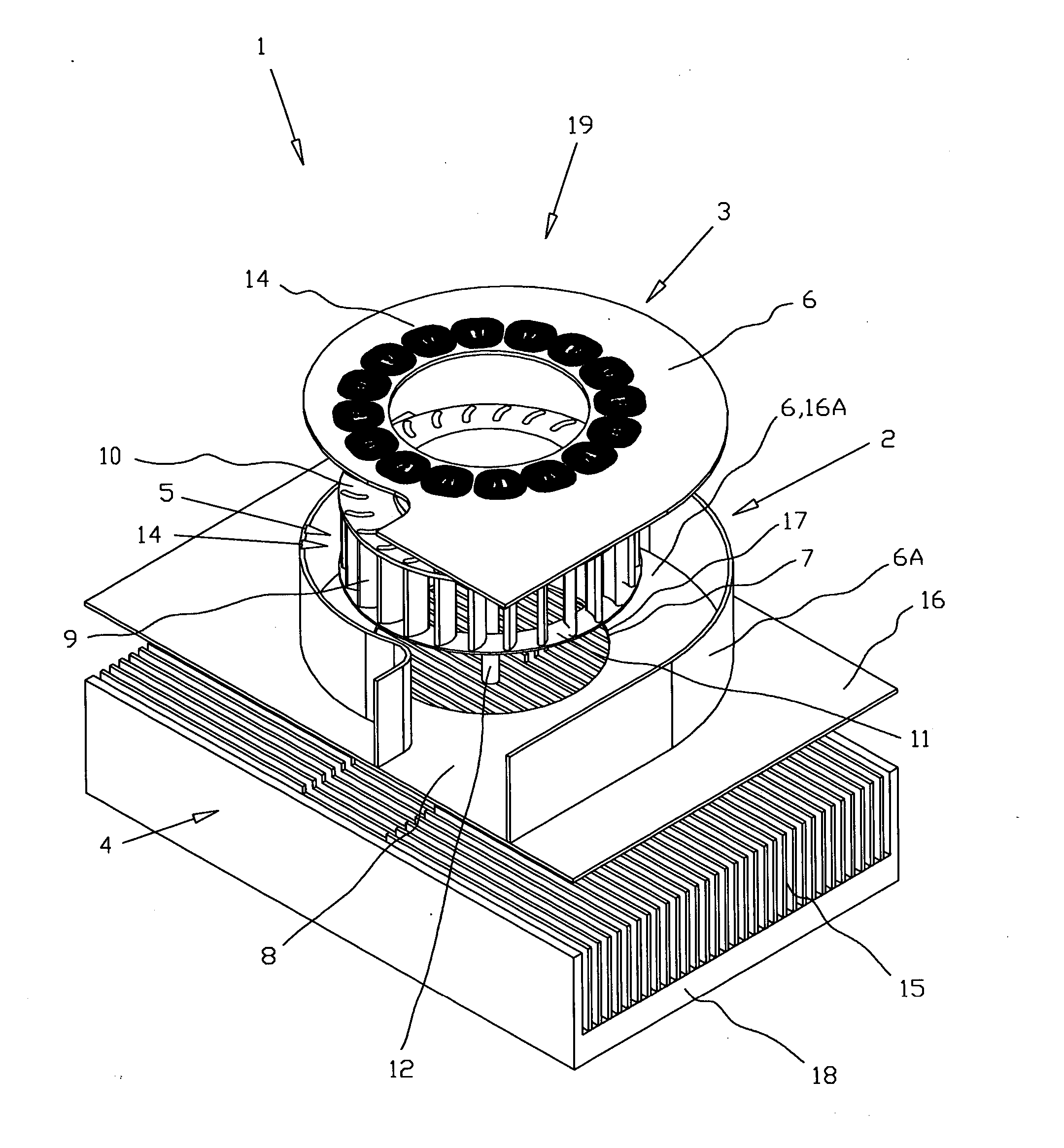
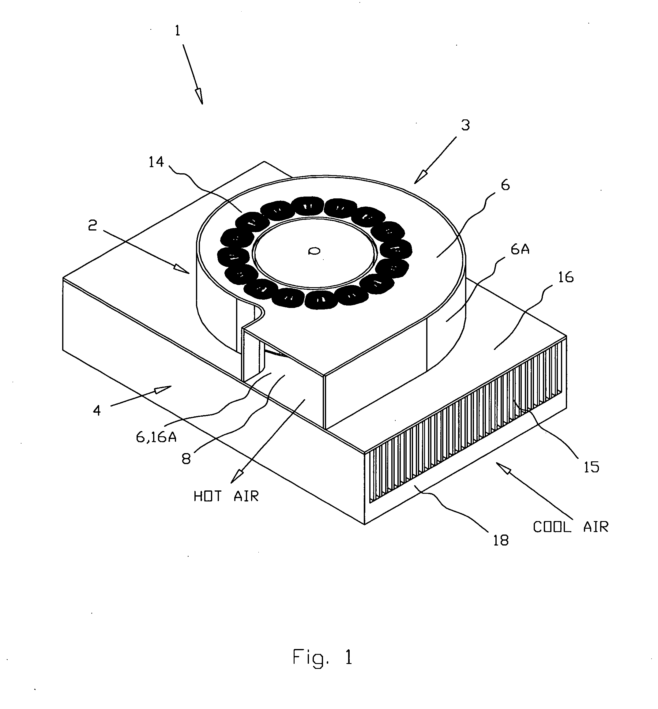
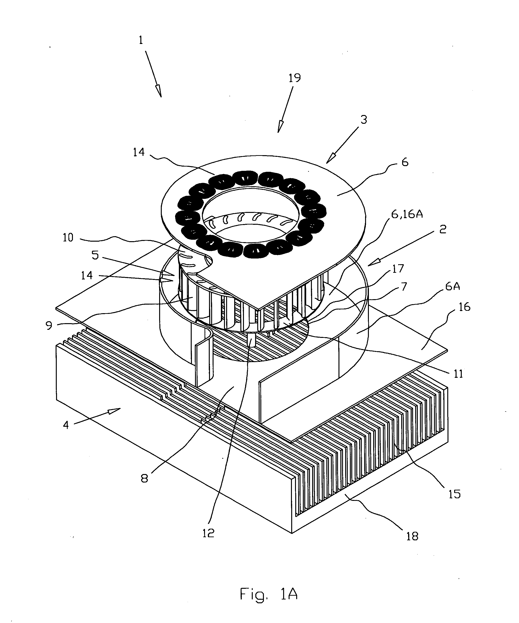
[0029] The integrated blade cooler 1 (FIGS. 1-6A) for electronic components (not shown) in all embodiments comprises a blower 2, an electric drive 3, and a heatsink 4. The blower 2 comprises a radial impeller 5 and a casing 6 with an inlet 7 and outlet 8. The radial impeller 5 that is made as a drum type impeller comprises magnetic blades 9, a backplate disk 10, a shroud 11 and an axis of rotation 12. The electric drive 3 comprises a magnetic rotor 13 and a stator 14 made as printed circuit board. The heatsink 4 comprises heat-exchanging means 15 clothed in a cover plate 16 with an outflow opening 17, and the base 18 providing the thermal contact with said electronic components and with the heat-exchanging means 15. The part 16A of the cover plate 16 is made as a part of the casing 6. As a result, outflow opening 17 of the heat...


PUM


Abstract

An integrated blade cooler for electronic components comprises a blower with a radial impeller and a casing, an electric drive with a magnetic rotor and a stator, and a heatsink with heat-exchanging means and a base providing thermal contact with said electronic component and said heat-exchanging means. The casing of the impeller has an inlet and an outlet; said impeller comprises blades, a backplate disk and an axis of rotation; and the heat-exchanging means of the heatsink clothed in a cover plate with an outflow opening that being coincided with said inlet so that cooling gas flows through said heat-exchanging means, said blower inlet, said radial impeller and said blower outlet in a series way. The stator of the electric drive is made as a part of said casing of the blower so that said outflow opening serves as said inlet, and the radial impeller comprises magnetic means serving as a magnetic rotor of said electric drive. The stator is made as printed circuit board. At least part of said cover plate is made as a part of said casing so that said outflow opening serves as said inlet of the blower. The stator is located perpendicularly to the axis of rotation, and said magnetic means magnetized in the direction parallel to said axis of rotation. The heatsink has a recess on the side of an outflow opening, and the blower is located in said recess.

Description

BACKGROUND OF THE INVENTION [0001] The present invention relates generally to cooling systems. More particularly, the present invention relates to cooling systems for regulating the temperature of electronic components of electronic devices. The present invention is particularly, but not exclusively, useful for cooling systems that regulate the temperature of electronic components of blade servers. [0002] The regulation of the temperature of electronic components like processors due to heat generated inside the housing of an electronic device like a blade server is an important consideration during the design of an electronic device. Cooling is important because if left unchecked, heat can cause electronic devices to malfunction during use or lead to premature device failure. As improvements in processor speed occur, the amount of heat generated by the faster processors also increases. Additionally, improved processors require larger power supplies and auxiliary components that gene...

Claims


Application Information

Patent Timeline
Patent Type & Authority Applications(United States)
IPC IPC(8): F04D25/06F04D29/58H02K7/14H02K21/24
CPCF04D25/066H02K21/24H02K7/14F04D29/582
Inventor FEDOSEYEV, LEVSCHAEFER, DANIELLOPATINSKY, EDWARDROSENFELD, SAVELIY
Owner ROTYS
Why Eureka
Try Eureka