Reagent dispenser and dispensing method

a technology of reagent dispenser and dispenser, which is applied in the direction of separation process, laboratory glassware, instruments, etc., can solve the problems of high cost, complex mechanical and electrical system, and sensitive chemical interaction between reagents, and achieve high system complexity, increase the coefficient of variation (cv), and high efficiency

Inactive Publication Date: 2005-02-10
AURORA DISCOVERY INC
View PDF5 Cites 7 Cited by
  • Summary
  • Abstract
  • Description
  • Claims
  • Application Information

AI Technical Summary

Benefits of technology

[0019] Each reagent is dispensed from a corresponding pressurized reagent container through a corresponding discrete fluid path. Each fluid path includes a fluid delivery line, a dispensing device for selectively dispensing the reagent, and a fluid tube. The fluid tubes terminate at corresponding dispensing tips where the reagents are dispensed into target wells, as described herein. The geometric arrangement of the dispensing tips as described herein allows for multiple reagent dispensing, while avoiding the pitfalls associated with known devices, e.g., increased coefficient of variation (CV) within each column of the microplate, substantial dead volume, and a high level of system complexity.
[0020] In particular, an array of dispensing tips produces accurate results in a timely manner. As used herein, an array refers to an array having at least 2 or more dispensing tips and not necessarily the same number of rows as columns. For simplicity, a rectangular array is 2×2 disclosed, which allows for dispensing of 2 or more reagents substantially simultaneo...

Problems solved by technology

In each of the aforementioned examples, the chemical interaction between the reagents may be quite sensitive, and the testing or screening procedures involve a very large number of discrete reactions.
This design has at least three drawbacks: 1) the use of 48 valves per reagent results in substantial variations in the reagent volume dispensed from each of the 48 tips due to subtle differences in the manufacturing of each valve dispenser; 2) the use of a fluid manifold results in a dead volume of reagent on the order of several milliliters, resulting in the waste of reagents; and 3) each individual reagent to be added requires its own bank of 48 valves resulting in a very complex mechanical and electrical system, increased equipment breakdown, and poor production efficiency.
However, 3,456 stop and go movements would be needed to fill the entire microplate, resulting in a significant increase in dispensing time.
Thu...

Method used


Image

  • Reagent dispenser and dispensing method
  • Reagent dispenser and dispensing method
  • Reagent dispenser and dispensing method

Examples


Embodiment Construction

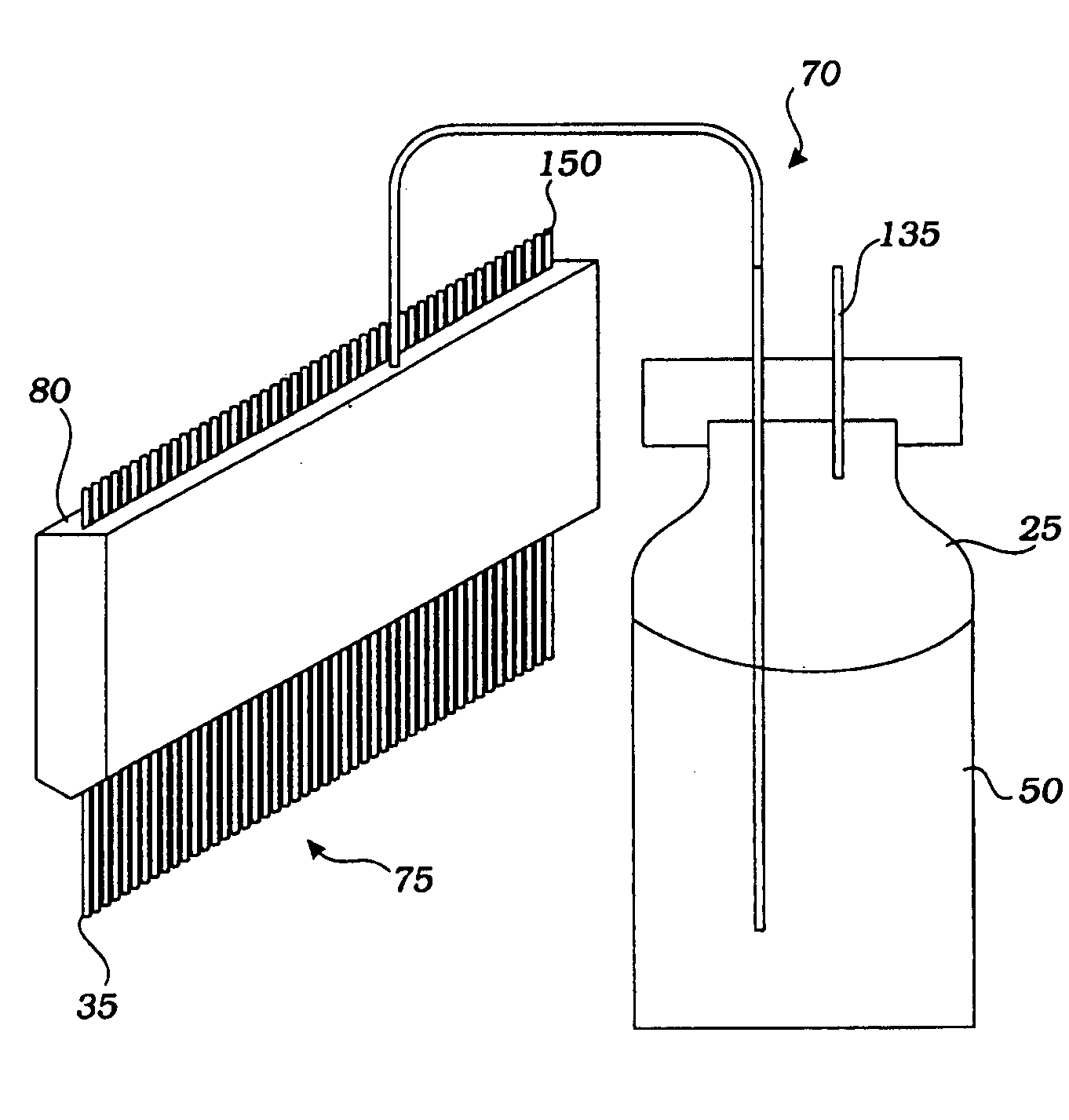
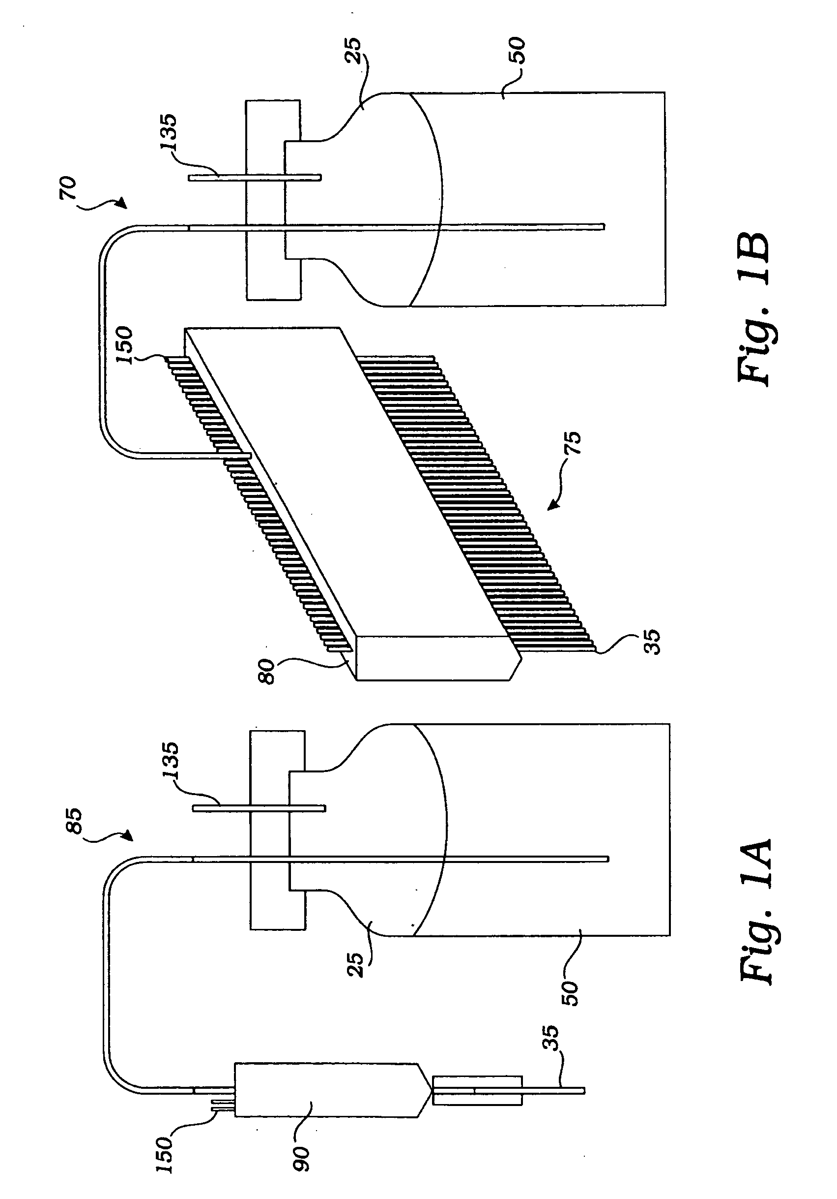
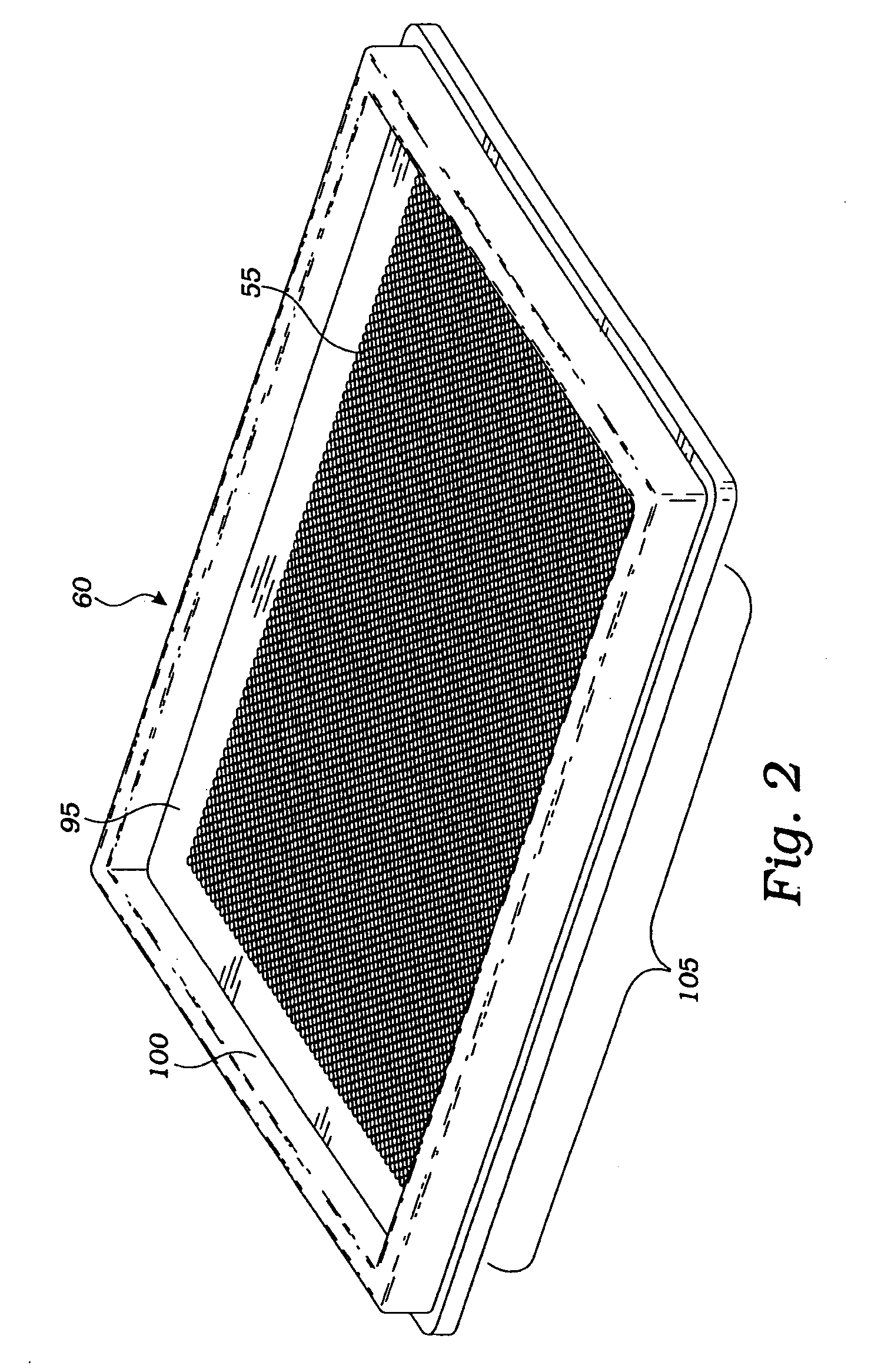
[0035] Embodiments of the invention will now be described with reference to the accompanying figures, wherein like reference numerals refer to like elements throughout. Unless otherwise expressly stated herein, the terminology used in the description presented herein is not intended to be interpreted in any limited or restrictive manner, simply because it is being utilized in conjunction with a detailed description of certain specific embodiments of the invention. Furthermore, embodiments of the invention may include several novel features, no single one of which is solely responsible for its desirable attributes or which is essential to practicing the inventions herein described.

[0036] As used herein, the terms “comprises,”“comprising,”“includes,”“including,”“has,”“having” or any other variation thereof, are intended to cover a non-exclusive inclusion. For example, a process, method, article, or apparatus that comprises a list of elements is not necessarily limited to only those e...


PUM

PropertyMeasurementUnit
Lengthaaaaaaaaaa
Fractionaaaaaaaaaa
Fractionaaaaaaaaaa

Abstract

A method and apparatus is disclosed for automated on-the-fly dispensing of reagents. The apparatus includes a detachable reagent dispensing module supported by a support frame. The dispensing module includes a self-contained pressurized fluid delivery subsystem that facilitates efficient attachment and detachment of the module, including pressurized reagent containers and associated accessories arranged such that each reagent container has a discrete fluid path terminating at a corresponding discrete reagent dispensing tip. The dispensing tips are supported in a common dispensing head, and are arranged geometrically such that the centers of the dispensing tips are separated by distances corresponding to relevant dimensions of particular assay plates to be used therewith. Such a geometric arrangement allows for dispensing of multiple reagents substantially simultaneously into multiple corresponding target wells of the assay plate, efficiently and precisely.

Description

INCORPORATION BY REFERENCE [0001] This application claims the benefit of U.S. Provisional Application No. 60 / 450,066 filed Feb. 26, 2003, the contents of which are incorporated by reference.BACKGROUND OF THE INVENTION [0002] 1. Field of the Invention [0003] The present invention relates generally to a method and apparatus for dispensing reagents and other liquids. More particularly, the present invention relates to a method and apparatus for delivering multiple reagents into an assay plate or other receptacle. [0004] 2. Description of the Related Art [0005] Many areas of scientific and medical research require dispensing reagents (any chemical or biological material that is a part of an assay) into assay plates. For example, medical diagnosis of and deciding upon a course of treatment for various diseases include the mixing of specific reagents with various bodily fluids in order to detect the presence or absence of a particular viral, bacterial, or other infectious constituent. Bio...

Claims


Application Information

Patent Timeline
IPC IPC(8): B01DB01J4/00B01L3/02G01N35/10
CPCB01J4/001B01L3/0241Y10T436/2575G01N35/1009G01N35/1074G01N35/1002
Inventor COASSIN, PETER J.FLORES, JAVIERNICOL, DAVIDPETERSON, TROYSALZMANN, PHILIPVUONG, T. MINH
Owner AURORA DISCOVERY INC
Why Eureka
Try Eureka