Mitral valve therapy device, system and method

a technology of mitral valve and therapy device, which is applied in the field of devices, systems and methods for treating deformed heart valves, can solve the problems of ineffective closure of mitral valve, leakage through the mitral valve and regurgitation, and impaired normal functioning of the mitral valve in preventing regurgitation

Inactive Publication Date: 2005-02-10
CARDIAC DIMENSIONS
View PDF99 Cites 210 Cited by
  • Summary
  • Abstract
  • Description
  • Claims
  • Application Information

AI Technical Summary

Problems solved by technology

The normal functioning of the mitral valve in preventing regurgitation can be impaired by dilated cardiomyopathy caused by disease or certain natural defects.
This can result in deformation of the mitral valve geometry to cause ineffective closure of the mitral valve during left ventricular contraction.
Such ineffective closure results in leakage through the mitral valve and regurgitation.
Diseases such as bacterial inflammations of the heart or heart failure can cause the aforementioned distortion or dilation of the mitral valve annulus.
While the replacement of the entire valve eliminates the immediate problem associated with a dilated mitral valve annulus, presently available prosthetic heart valves do not possess the same durability as natural heart valves.
While the prior art methods mentioned above have been able to achieve some success in treating mitral regurgitation, they have not been without problems and potential adverse consequences.
Such procedures are expensive, are extremely invasive requiring considerable recovery time, and pose the concomitant mortality risks associated with such procedures.
Moreover, such open heart procedures are particularly stressful on patients with a comprised cardiac condition.
Further, the effectiveness of such procedures is difficult to assess during the procedure and may not be known until a much later time.
Hence, the ability to make adjustments to or changes in the prostheses to obtain optimum effectiveness is extremely limited.
Unfortunately, the human anatomy does impose some obstacles to this recently proposed procedure for treating mitral regurgitation.
As a result, a device placed in the coronary sinus must not be permitted to extend within the coronary sinus beyond the crossover point of the circumflex artery and the coronary sinus to avoid constriction of the circumflex artery.

Method used


Image

  • Mitral valve therapy device, system and method
  • Mitral valve therapy device, system and method
  • Mitral valve therapy device, system and method

Examples


Embodiment Construction

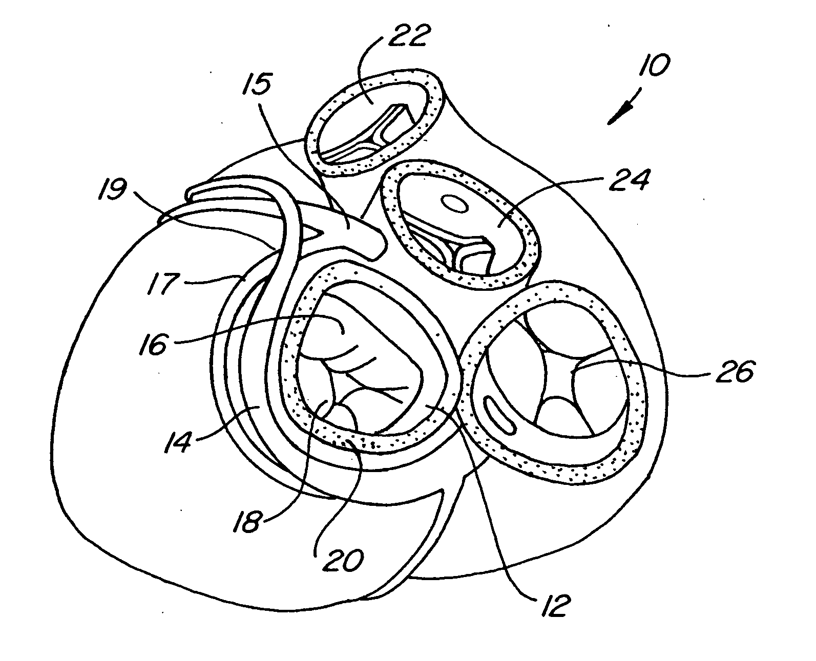
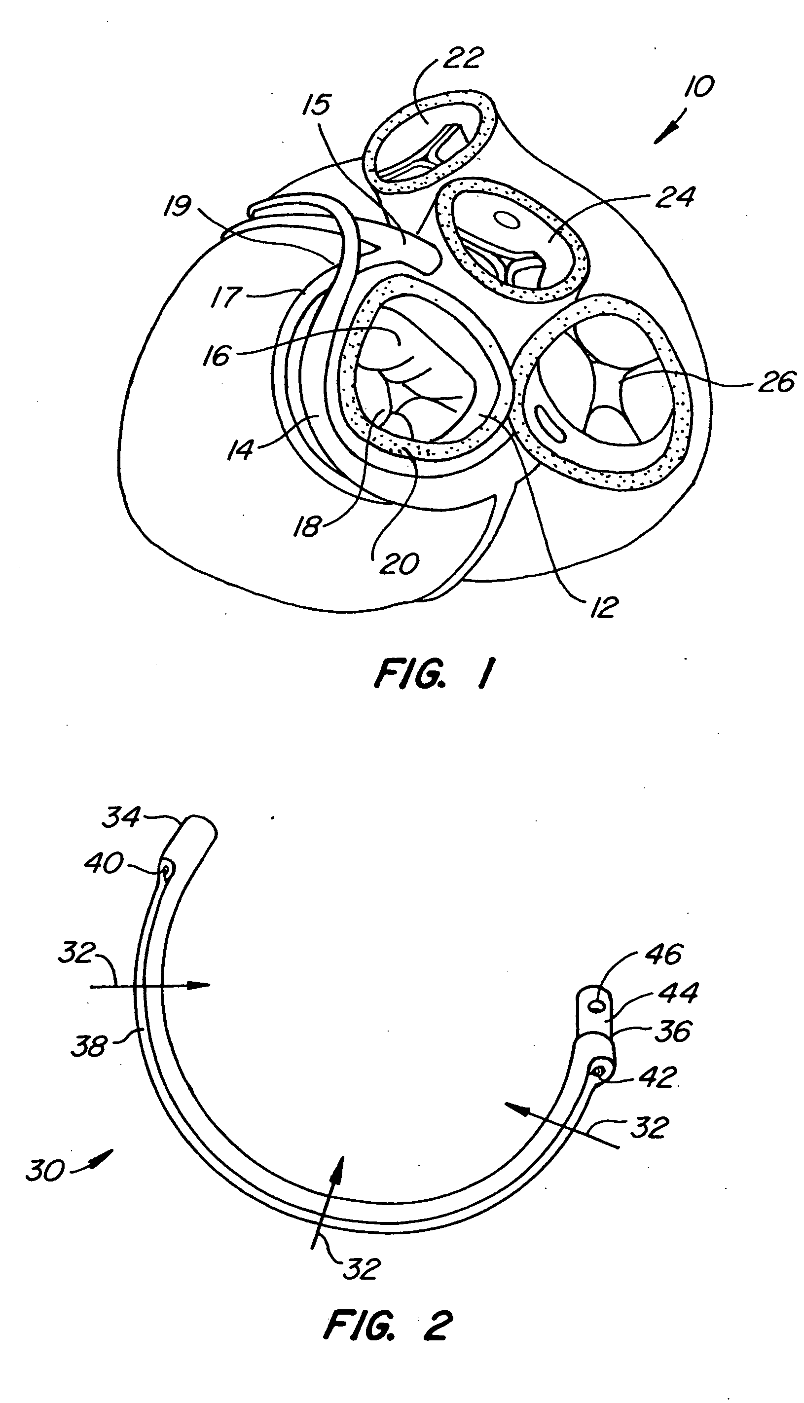
[0045] Referring now to FIG. 1, it is a superior view of a human heart 10 with the atria removed to expose the mitral valve 12, the coronary sinus 14, the coronary artery 15, and the circumflex artery 17 of the heart 10 to lend a better understanding of the present invention. Also generally shown in FIG. 1 are the pulmonary valve 22, the aortic valve 24, and the tricuspid valve 26 of the heart 10.

[0046] The mitral valve 12 includes an anterior cusp 16, a posterior cusp 18 and an annulus 20. The annulus encircles the cusps 16 and 18 and maintains their spacing to provide a complete closure during a left ventricular contraction. As is well known, the coronary sinus 14 partially encircles the mitral valve 12 adjacent to the mitral valve annulus 20. As is also known, the coronary sinus is part of the venus system of the heart and extends along the AV groove between the left atrium and the left ventricle. This places the coronary sinus essentially within the same plane as the mitral val...


PUM


Abstract

An assembly and method for effecting the condition of a mitral valve annulus of a heart includes a guide wire configured to be fed into the coronary sinus of the heart, and a mitral valve annulus therapy device configured to be slidingly received on the guide wire and advanced into the coronary sinus of the heart on the guide wire. A guide tube may further be employed for guiding the device into the coronary sinus. An introducer which may be employed for pushing the device into or pulling device out of the heart has a mechanism for releasably locking to the device. This enables substitution of the device if needed. Also, the crossover point of the circumflex artery and coronary sinus may be determined and avoided when the device is deployed.

Description

FIELD OF THE INVENTION [0001] The present invention generally relates to a device, system and method for treating a deformed heart valve. The present invention more particularly relates to a device, system and method for constricting or reforming a mitral valve annulus from within the coronary sinus to correct mitral valve dilation without blocking blood flow in the circumflex artery and which may be implemented using a guide wire within the coronary sinus to effect accurate device deployment and substitution. BACKGROUND OF THE INVENTION [0002] The human heart generally includes four valves. Of these valves, a most critical one.. is known as the mitral valve. The mitral valve is located in the left atrial ventricular opening between the left atrium and left ventricle. The mitral valve is intended to prevent regurgitation of blood from the left ventricle into the left atrium when the left ventricle contracts. In preventing blood regurgitation the mitral valve must be able to withstan...

Claims


Application Information

Patent Timeline
Patent Type & Authority Applications(United States)
IPC IPC(8): A61F2/24
CPCY10S623/904A61F2/2451
Inventor ALFERNESS, CLIFTON A.ADAMS, JOHN M.POWER, JOHN MELMOTH
Owner CARDIAC DIMENSIONS
Why Eureka
Try Eureka