Machining apparatus

Inactive Publication Date: 2005-02-17
KONICA MINOLTA OPTO
View PDF9 Cites 11 Cited by
  • Summary
  • Abstract
  • Description
  • Claims
  • Application Information

AI Technical Summary

Benefits of technology

[0019] In contrast with this, according to this invention, by forming the above-mentioned first workbench of a ceramic material, in comparison, for example, with a conventional workbench made of cast iron, its weight can be reduced by a large margin and its

Problems solved by technology

Therefore, because the workbench becomes heavy, and the power of a servomotor required for driving this becomes high, there has been a problem that the quantity of heat generation from this motor becomes large.
Further, because it has not been possible to move the workbench at a high speed, there has been also a problem that the speed of machining becomes slow, which makes the machining time longer, and if a variation of the environment such as the te

Method used


Image

  • Machining apparatus
  • Machining apparatus
  • Machining apparatus

Examples


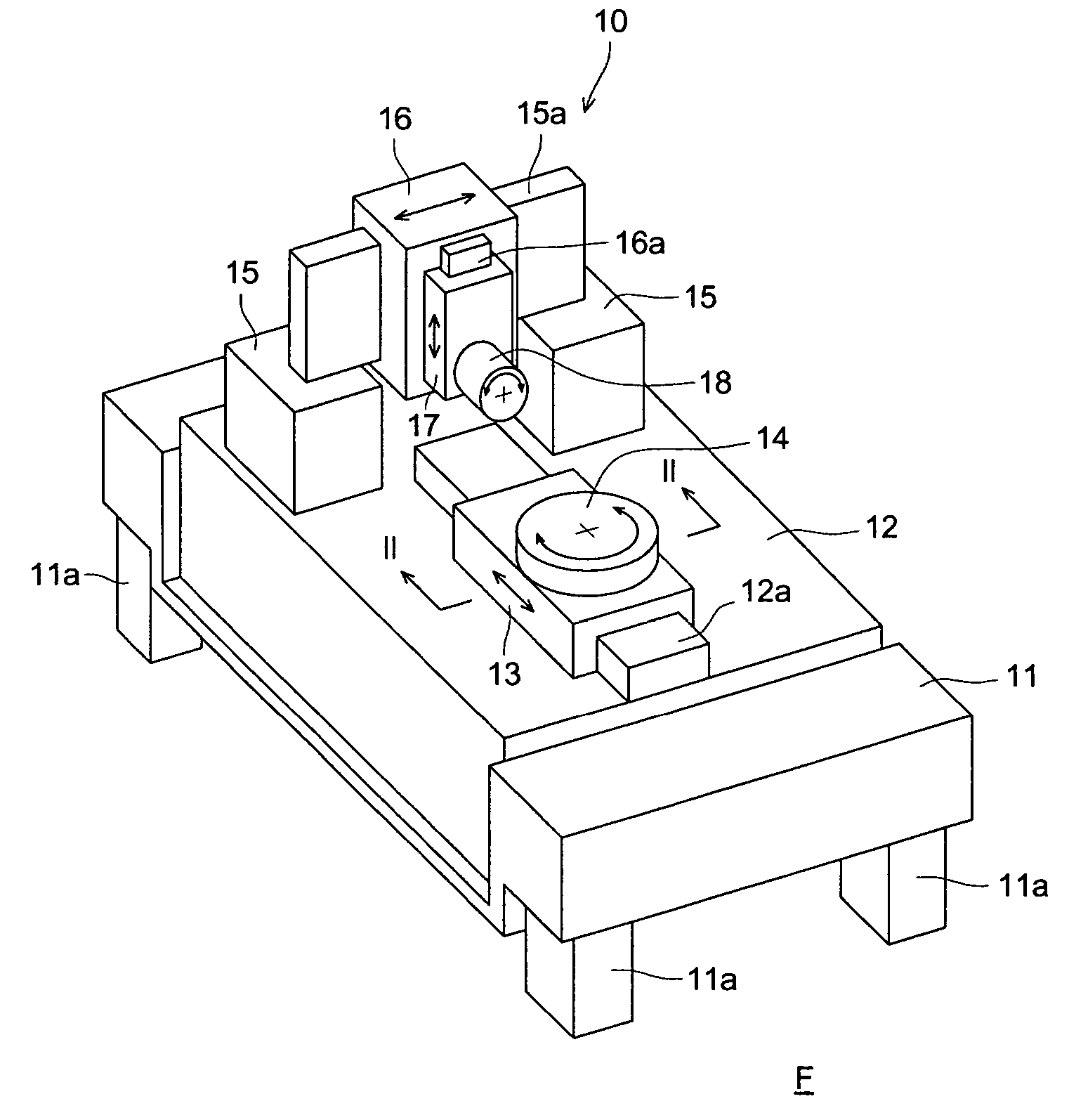
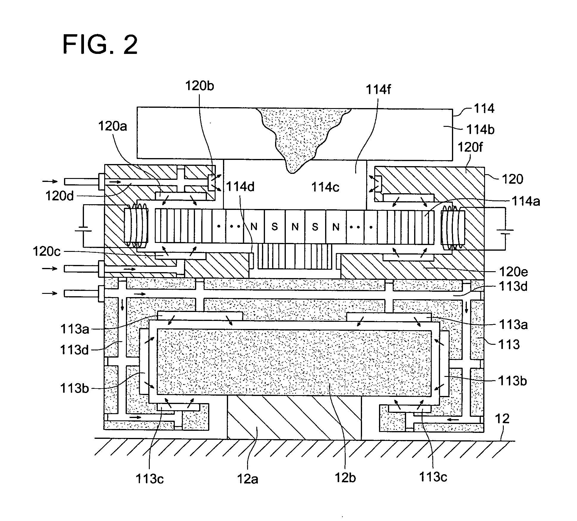
Embodiment Construction

[0024] Firstly, the preferable structures according to the present invention are explained.

[0025] A machining apparatus set forth in Item (2) is a machining apparatus as set forth in the Item (1), wherein the aforesaid ceramic material has a coefficient of linear expansion of 5×10⁻⁶ K−1 or less; therefore, as compared to cast iron, its thermal expansion can be suppressed to be low by half or less; therefore, the accuracy of machining can be maintained secured while the acceleration ability is made higher owing to its weight being made lighter, which makes it possible to shorten the machining time.

[0026] A machining apparatus set forth in Item (3) is a machining apparatus as set forth in the Item (1) or (2), wherein the aforesaid ceramic material contains silicon nitride of 50% or more by weight as converted into Si3N4 and has a specific weight of 4 g / cm3; therefore, the weight of the aforesaid workbench becomes a half or less of a conventional one, and even if the power of the axi...


PUM

PropertyMeasurementUnit
Percent by massaaaaaaaaaa
Pressureaaaaaaaaaa

Abstract

A machining apparatus for conducting at least one of a cutting process and a grinding process, comprises a stationary base; and a working device mounted on the stationary base and having a degree of freedom of more than two axes to conduct at least one of a cutting process and a grinding process, the working device comprising a first working bench which is formed of a ceramic material and is movable linearly with a degree of freedom of not less than one axes or more while holding a work piece or a tool.

Description

BACKGROUND OF THE INVENTION [0001] This invention relates to a machining apparatus having a degree of freedom of machining of three axes or greater. [0002] Herein, the term “axes” or “an axis” is defined as a portion of a machining apparatus that functions as the reference line or plane of a movement for machining, for example, the rotary shaft of a swivel table, the slideway of a slide table, etc. The degree of freedom of movement for machining is one for each of the “axes”. [0003] A machining apparatus for applying cutting machining, grinding machining, or the like to an optical element and a die for the formation thereof is known (refer to the patent literature 1). [0004] [Patent literature 1] The publication of the unexamined patent application 2003-39294. [0005] In this connection, in order to generate a complex curved surface corresponding to an aspherical surface of an optical element with a high accuracy, a degree of freedom of machining of two or less is insufficient, and a...

Claims


Application Information

Patent Timeline
IPC IPC(8): B23Q1/26B23Q1/38B23Q1/48B24B13/00B23Q1/00B24B13/06
CPCB23Q1/38B23Q1/4852B24B13/06Y10T409/309576Y10T409/305656Y10T29/511Y10T409/304312Y10T29/5114H05B6/6482H05B6/76
Inventor HOSOE, SHIGERU
Owner KONICA MINOLTA OPTO
Why Eureka
Try Eureka