Raceway construction for an air handling unit

Inactive Publication Date: 2005-02-17
YORK INT
View PDF68 Cites 40 Cited by
  • Summary
  • Abstract
  • Description
  • Claims
  • Application Information

AI Technical Summary

Benefits of technology

[0015] An advantage of the present invention is a sloped roof assembly that prevents the collection of standing water.
[0016] A further advantage of the present invention is a raceway construction that is symmetric about a plane of symmetry, permitting a single raceway construction.
[0017] A further advantage of the present invention is the provision of raceways having both a low thermal conductivity and high mechanical strength properties for use with lifting the AHU.
[0018] A further advantage of the present invention is th

Problems solved by technology

AHUs are typically large and bulky, the amount of floor space required to accommodate the AHU being commonly referred to as a “footprint.” Due to the layout of a particular structure, the AHU may be located in any number of locations, including rooftop installations, wherein the AHU is exposed to the rigors of environmental exposure, such as rain or snow.
Due to the bulky construction the AHUs, it is generally not possible to deliver the AHU fully assembled.
This imposed size restriction often results in the severing of otherwise continuous spans of the raceways, which severed ends of the raceways being referred to as “splits.” Such splits interrupt the structural integrity of the raceways and further complicate AHU on-site installation.
To further complicate matters, raceways are typically constructed of non-metal materials having lower mechanical strength properties, generally rendering non-metal raceways nonusable for attaching lugs to provide a means for lifting the modular unit, much less the entire AHU once assembled.
The higher thermal conductivity of typical metallic raceways may not only decrease the efficiency of the heating and cooling system, but may also result in the production of condensation in or adjacent the raceways, further promoting corrosion of the metallic raceways.
These stiffening members add compo

Method used


Image

  • Raceway construction for an air handling unit
  • Raceway construction for an air handling unit
  • Raceway construction for an air handling unit

Examples


Embodiment Construction

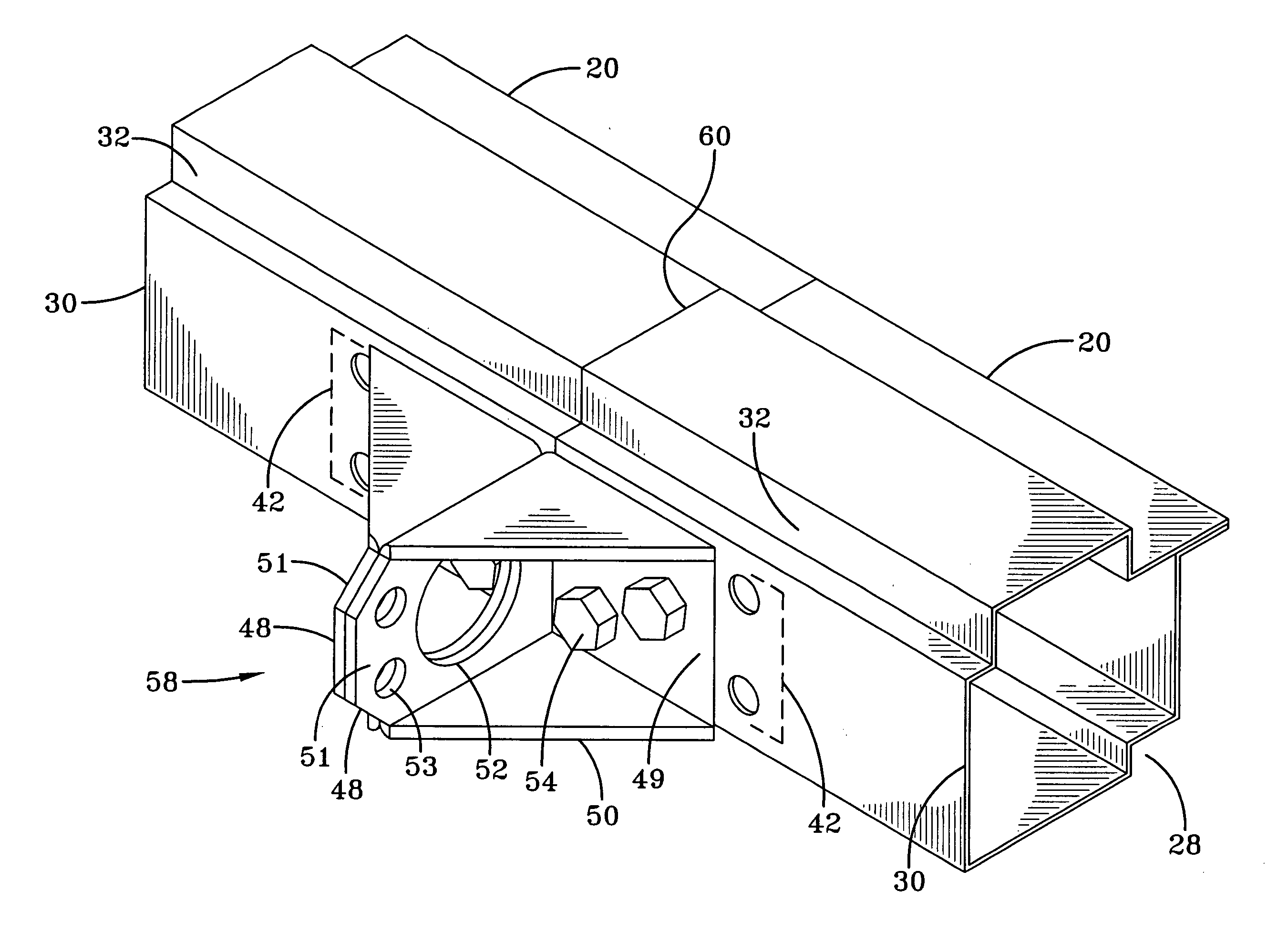
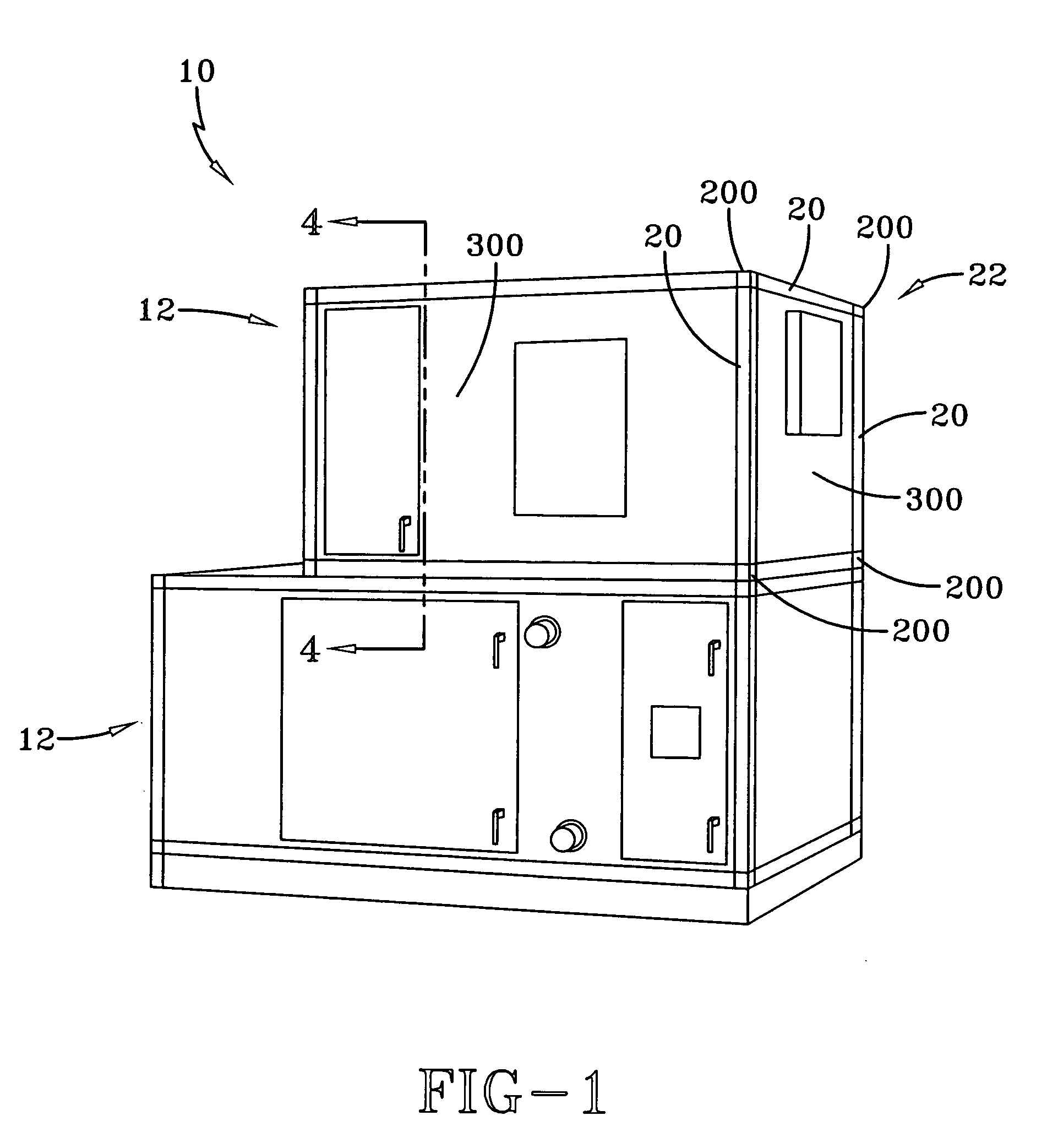
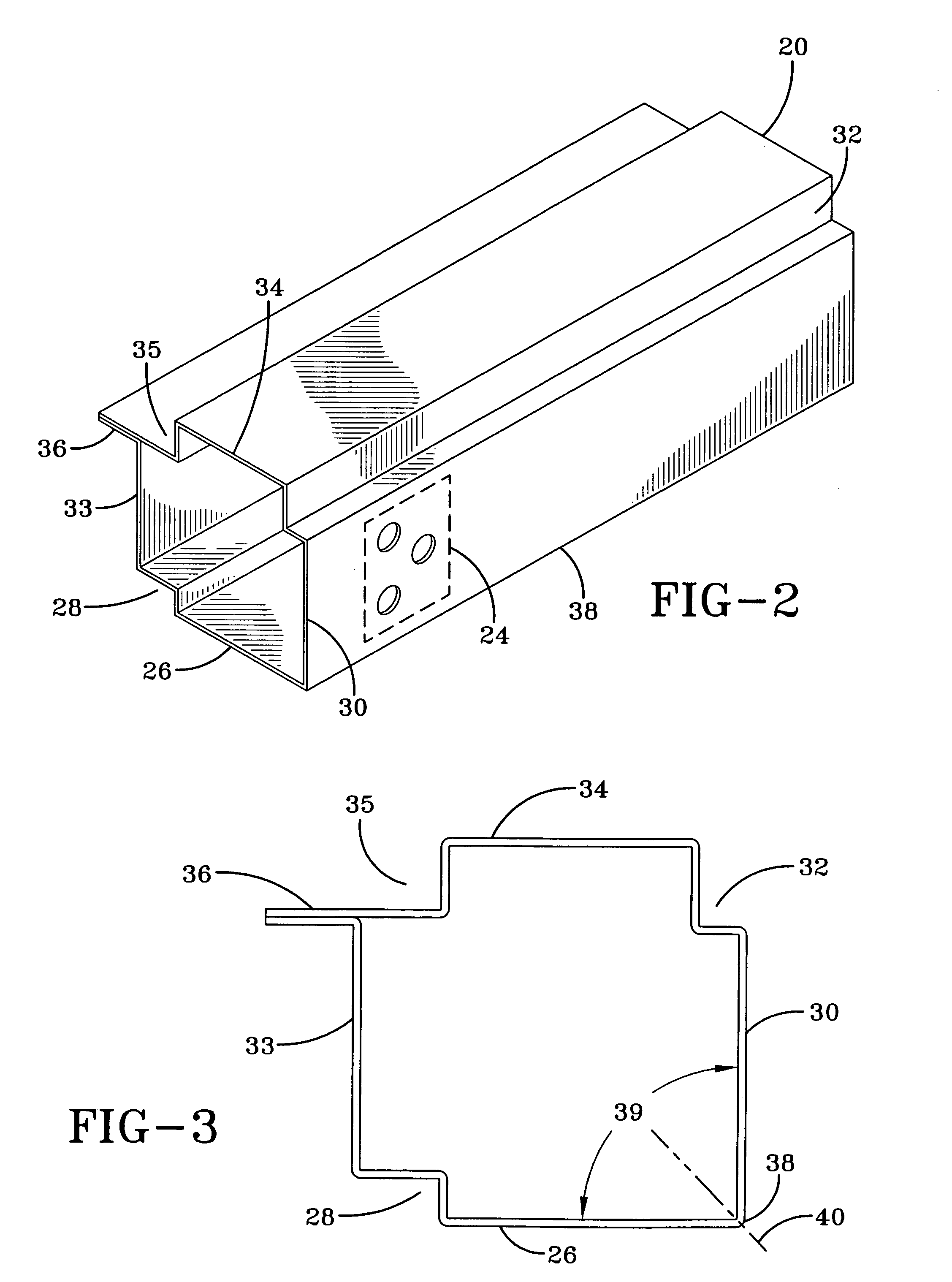
[0065] The present invention relates to framing members that are comprised of interconnected raceways which are adapted to both structurally and sealingly carry rectangular insulated panels. Having a closed cross sectional profile, the raceway is sufficiently stiff to satisfy the most rigorous structural loading requirements, while maintaining a lightweight construction. The raceway has a single profile that is configured to be used regardless of whether the raceway defines a lower horizontal, upper horizontal, left vertical or right vertical frame member for surrounding the rectangular panel. The raceway also provides an identical, continuous seam or recess for securing each side of the panel. Additionally, the raceway may be provided with a universal aperture arrangement adjacent to its ends for use with the appropriate connectors to permit splicing and / or lifting points at the corners of the AHU structure or at any position along the span of the raceway.

[0066] The raceway define...


PUM


Abstract

An air handling unit (AHU) for housing a number of components used in a heating or cooling system to provide forced air for climate control in a particular structure includes a single raceway construction having both low thermal conductivity and enhanced mechanical properties for use with lifting the AHU; a single insulated panel construction having a minimum number of components as well as enhanced mechanical properties for use as the floor in an AHU compartment; to minimize costs associated with fabrication and installation.

Description

CROSS REFERENCE TO RELATED APPLICATIONS [0001] This Application claims the benefit of U.S. Provisional Application No. 60 / 495,042, filed Aug. 14, 2003, and is related to application Ser. No. ______, Attorney Docket No. 20712-0098, filed contemporaneously with this Application on Aug. 12, 2004, entitled “CORNER CAP MEMBER CONSTRUCTION FOR AN AIR HANDLING UNIT” assigned to the assignee of the present invention and which is incorporated herein by reference, to application Ser. No. ______, Attorney Docket No. 20712-0099, filed contemporaneously with this Application on Aug. 12, 2004, entitled “CORNER ASSEMBLY CONSTRUCTION FOR AN AIR HANDLING UNIT” assigned to the assignee of the present invention and which is incorporated herein by reference, to application Ser. No. ______, Attorney Docket No. 20712-0100, filed contemporaneously with this Application on Aug. 12, 2004, entitled “PANEL CONSTRUCTION FOR AN AIR HANDLING UNIT” assigned to the assignee of the present invention and which is in...

Claims


Application Information

Patent Timeline
IPC IPC(8): E04B1/24E04B1/348E04B1/58E04C2/292E04F17/04E04H5/02F24F3/044F24F13/20
CPCE04B1/3483E04B1/5825E04B2001/2415E04B2001/2451E04B2001/2457E04B2001/2481F24F13/20E04C2/292E04F17/04E04H5/02E04H2001/1283F24F3/0442E04B2001/2484E04B1/7633
Inventor DUBENSKY, HAROLD J.JIA, JACK YUERUNKLE, DENNIS R.PIERJOK, WAYNE JOSEPHSMITH, DENNIS WAYNEWEATHERD, MARTIN DALESTEIN, KEVIN LEEPEARS, NATHAN E.DIAMOND, DENNIS TIMOTHYEDGELL, ROBERT H.
Owner YORK INT
Why Eureka
Try Eureka