

Optical element, lens and optical head device
- Summary
- Abstract
- Description
- Claims
- Application Information
AI Technical Summary
Benefits of technology
Problems solved by technology
Method used
Image

Examples
first embodiment
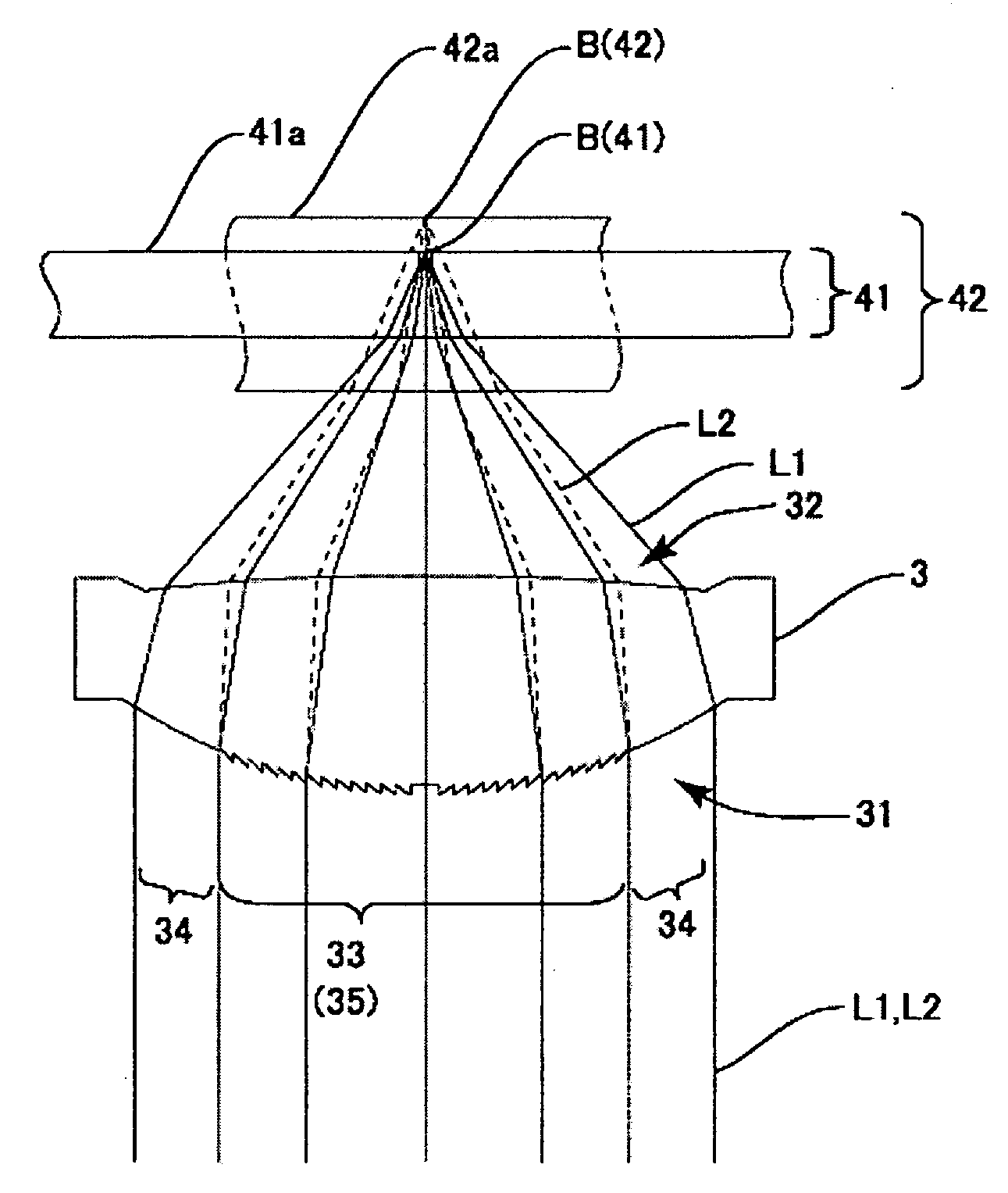
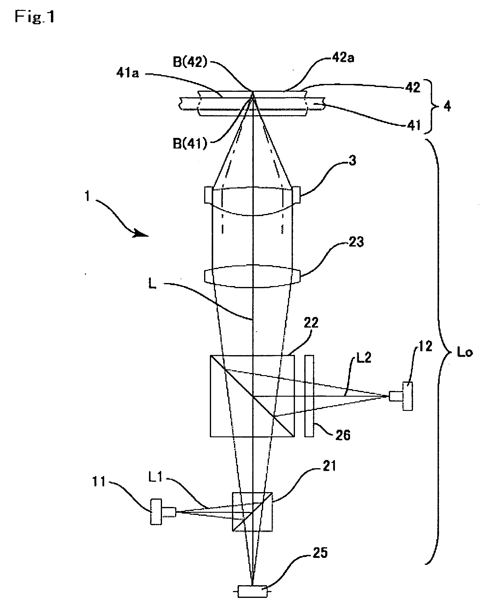
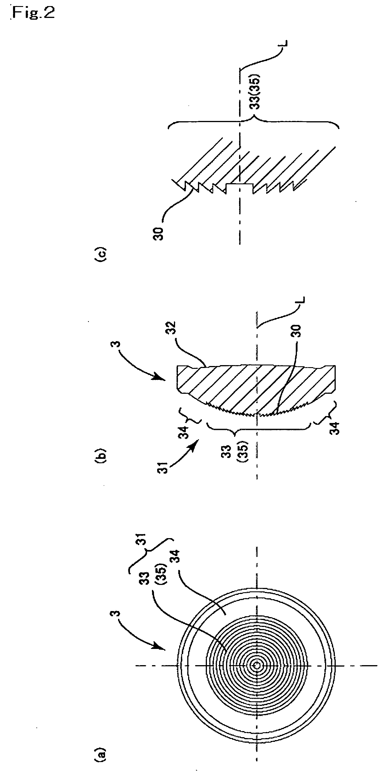
FIG. 2(a) is a plan view of the objective lens to which the present invention is applied, FIG. 2(b) is its cross-sectional view and FIG. 2(c) is a partly enlarged cross-sectional view of the inner side refraction face region of an incident side refraction surface of the objective lens shown in FIG. 2(b). FIG. 3 is an explanatory side view showing converging states of the first and the second laser beams with the use of the objective lens shown in FIGS. 2(a)-2(c).
The objective lens 3 shown in FIGS. 2(a), 2(b) and 2(c) is a convex lens provided with an incident side refraction surface 31 having a positive power, to which the laser beams L1, L2 emitted from the first laser light source 11 and the second laser light source 12, respectively, are incident, and an emitting side refraction surface 32 from which the laser beam is emitted toward the optical recording medium 4. Each of the incident side refraction surface 31 and the emitting side refraction face 32 is provided with a prescrib...
second embodiment
FIGS. 4(a), 4(b), 4(c) and 4(d) are views of the objective lens in which a diffraction grating is also formed on the outer side refraction surface region. FIG. 4(a) is a plan view of the objective lens, FIG. 4(b) is its cross-sectional view, and FIGS. 4(c) and 4(d) are partly enlarged cross-sectional views of the objective lens shown in FIG. 4(b).
In the objective lens 3 according to the first embodiment described with reference to FIGS. 2(a)-2(c), the beam spot by using the beam component of the first laser light beam passing through the outer side refraction face region 34 is formed on the recording surface of the DVD 41 by setting the refracting power of the outer side refraction face region 34 to an appropriate value. Alternatively, according to the second embodiment of the present invention, the diffraction grating may be also formed on the outer side refraction face region 34 such that the beam spot of the diffracted light beam component of the first laser beam L1 passing thro...
PUM
 Abstract
Description
Claims
Application Information