Precise common timing in a wireless network

a wireless network and frequency technology, applied in the field of wireless communication networks, can solve the problems of increasing cost and deployment time, requiring additional hardware for gsm lmus, and expensive additions, and achieve the effect of improving the gps positioning capability and performance of mobile units

Inactive Publication Date: 2005-02-17
NOKIA SIEMENS NETWORKS GMBH & CO KG
View PDF5 Cites 135 Cited by
  • Summary
  • Abstract
  • Description
  • Claims
  • Application Information

AI Technical Summary

Benefits of technology

It is another purpose of the invention to improve GPS positioning capability and performance for mobile units;

Problems solved by technology

GSM LMUs tend to require additional hardware and are expensive additions in any wireless network.
Moreover, in order to synchronize the transmission timing of every wireless network base station with a common timing source, it may be necessary to deploy a separate measurement unit for every base station, or every few base stations, thereby further increasing cost and deployment time.

Method used


Image

  • Precise common timing in a wireless network
  • Precise common timing in a wireless network
  • Precise common timing in a wireless network

Examples


Embodiment Construction

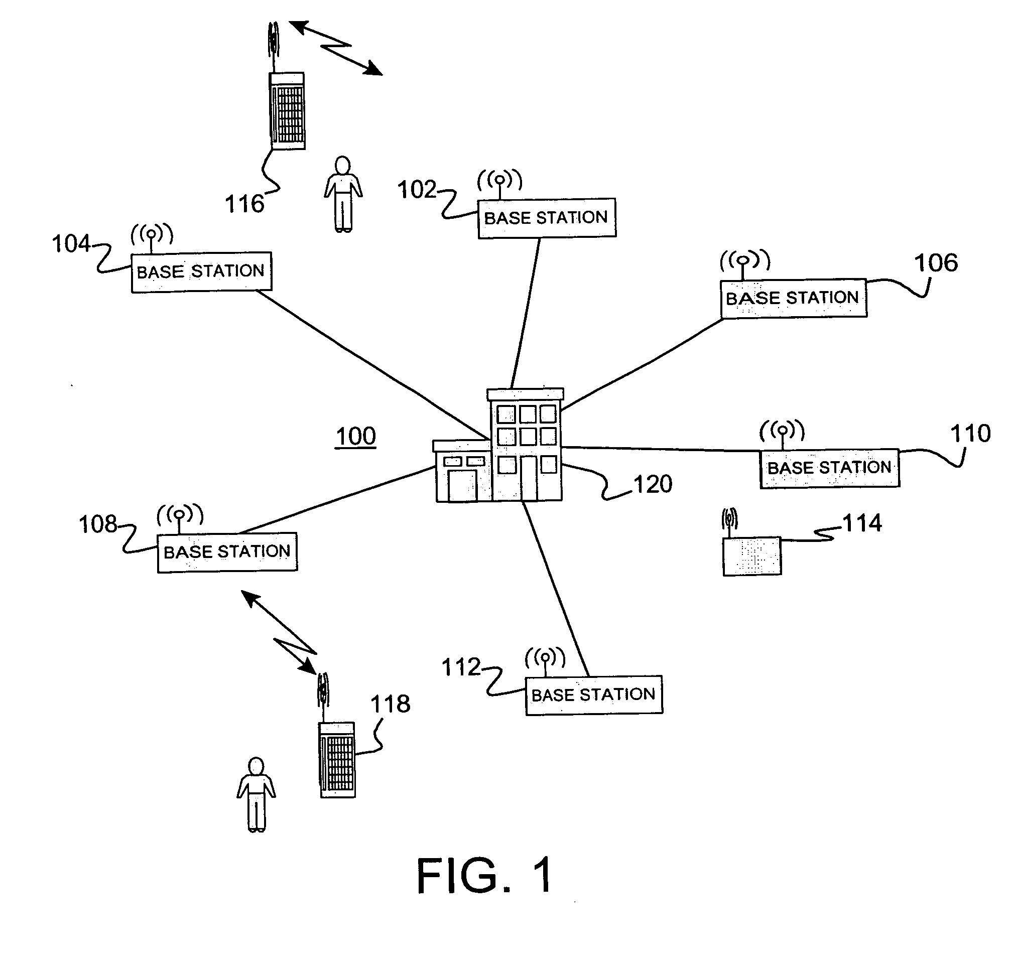
Turning now to the drawings and, more particularly, FIG. 1 shows an example of a preferred embodiment wireless network 100 or system, e.g., a Global System for Mobile Communication (GSM) network, a Time Division Multiple Access (TDMA) network, Code Division Multiple Access (CDMA) network or an equivalent network. One or more timing marker units or timing markers 114 at known locations are dispersed throughout the system or subsystem reception area. The wireless network 100 serves mobile stations or units 116, 118 within reception range of at least one of the base stations 102, 104, 106, 108, 110, 112. Mobile units 116, 118 may include cellular phone handsets (cell phones) or other devices with a wireless communications interface, e.g., a computing device such as a personal digital assistant (PDA), laptop computer or tablet computer etc. Base station transceivers (BTS), also commonly referred to simply as “base stations”, 102, 104, 106, 108, 110, 112 are connected to a central entit...


PUM


Abstract

A method of providing precise common timing in a wireless communications network including at least one timing marker unit with a precise common time source, e.g., GPS. Wireless mobile units and/or timing marker units periodically measure transmission timing differences between pairs of neighboring base stations and each provide the measurements to a base station or central network entity. Timing marker units measure timing associations and return the results. An absolute transmission timing difference (ATD) is determined for each base station timing difference measurement. ATDs are collected and combined for each pair of base stations. A timing relationship is developed for all base stations from the combined ATDs, relating transmission timing of non-reference base stations to reference base stations. Timing associations are extracted for non-reference base stations from these timing difference relationships and the timing associations for the reference base stations.

Description

BACKGROUND OF THE INVENTION 1. Field of the Invention The present invention is related to wireless communications networks and, more particularly, to distributing precision timing throughout a wireless network. 2. Background Description A number of applications currently exist within wireless communication systems, such as those supporting Global System for Mobile Communication (GSM), Time Division Multiple Access (TDMA), Code Division Multiple Access (CDMA) and Universal Mobile Telecommunications System (UMTS) technologies, for which precise common timing information is needed by mobile units and by other entities in the wireless network. Examples of such applications include Global System for Mobile Communication (GSM) positioning and assisted GPS (A-GPS) positioning. Mobile units with A-GPS acquire and measure signals from a number of GPS satellites in order to obtain an accurate estimate of their current geographic position. It is well known that precise knowledge of GPS tim...

Claims


Application Information

Patent Timeline
Patent Type & Authority Applications(United States)
IPC IPC(8): H04B7/005H04B7/26
CPCH04W56/0015H04W56/006H04W56/002
Inventor EDGE, STEPHEN WILLIAM
Owner NOKIA SIEMENS NETWORKS GMBH & CO KG
Why Eureka
Try Eureka