
Injector

a technology of injectors and power injectors, which is applied in the field of injectors, can solve the problems of high cost, prohibitive cost, and high price of large power injectors, and achieve the effects of reducing or eliminating power connections to the injector, improving the power injector, and facilitating the attachment of a syring

Inactive Publication Date: 2005-02-17
LIEBEL FLARSHEIM CO
View PDF99 Cites 24 Cited by
  • Summary
  • Abstract
  • Description
  • Claims
  • Application Information

AI Technical Summary

Benefits of technology

Accordingly, to improve power injectors, there is need for an injector system including an injector in which pressure limits may be easily set within safety thresholds. It would be further desirable to provide an injector which allows for manipulation of injection speeds, rates, and / or pressures during the injection procedure. Further, it would be desirable to provide an injector which reduces or eliminates power connections to the injector itself. It would also be desirable to provide an injector to facilitate attachment of a syringe. Further, it would be desirable to provide an injector which has the capability of warming and / or maintaining the temperature of the media or other fluid to be injected. Additionally, it would be desirable to provide an injector which is capable of communicating with other injectors. Further, it would be desirable to provide an injector which is capable of tracking the location of the drive ram while reducing the overall size, and thus the cost, of the injector. Also, it would be desirable to provide an injector which includes a uniform or “soft” power switch associated with a peripheral component, such as a remote console. Further, it would be desirable to provide an injector which prevents rotation of the drive ram. Also, it would be desirable to provide an injector which improves the ease of its operation. And finally, it would be desirable to provide such an injector at low cost in order to provide such injectors to currently unavailable markets.
The injector of the present invention also includes a structure to prevent rotation of the drive ram. In particular, this prevents the ram from rotating about its axis of symmetry during an injection procedure. The anti-rotation of the ram is caused by the shape of the drive ram itself. In one embodiment, a cross-section of the drive ram taken perpendicular to the longitudinal axis of the drive ram is in the shape of back to back D's, having a flat surface across the top of the ram, a flat surface across the bottom of the ram and a curved surface on both sides of the ram. This drive ram inserts through a similarly shaped orifice 134 in a plate in the end of the housing of the injector of the present invention nearest the syringe. Due to the flat surfaces on the top and the bottom of the drive ram, the ram is thus unable to rotate as it moves forward. This is important in keeping a coupling element that is disposed at the end of the drive ram aligned in an upward facing direction so that syringes may be removed and replaced into the injector.

Problems solved by technology

There exist many drawbacks to the large injector units described above, which are presently used to inject contrast media and other media.
For example, these large power injectors generally are only available at a high cost.
In many instances, this cost is prohibitive in that it prices many of these injectors out of the range of some small hospitals, and out of the range of developing and third world markets.
Also, this results in injection procedures wherein the contrast media, or other fluid, is delivered by a hand syringe, which is ergonomically unsafe and can lead to cumulative stress disorders for the user.
Further, the use of a hand syringe provides inferior images as compared to those generated when using a power injector.
Additionally, many costly, large injector units may include a number of features which may not be necessary for the purposes for which they are to be used at some smaller hospitals and other medical facilities.
In addition to the cost concerns discussed above, safety concerns can arise due to the use of these large, and often complex, injectors.
First, these injectors operate at a relatively high pressures, as described above.
For example, access ports are inserted into patients who need medication intravenously, but whose veins cannot tolerate multiple needle sticks.
Access ports that are implanted into patients cannot tolerate many of the high pressures capable of being generated by these large injectors.
High flow rates and pressures can cause the implanted catheter portion of the access port to break and require surgery to remove.
Thus, unless the pressure of such an injector is manually reduced, the access ports in a patient can be become over-pressured and possibly fail.
If the technologist forgets to reset the limit to the higher setting once the application has been performed, the desired flow rates may not be achieved during injections for subsequent patients.
This can result in ineffective injections and a waste of media, among other costs attendant to repeating the injection procedure.
This lack of control over the pressure and flow rates at which an injection proceeds may raise safety issues for the patient or other subject being injected, should an incorrect pressure limit or flow rate be programmed.
Likewise, halting an injection procedure can result in ineffective injections and waste of media, among other costs.
Additional problems arise when attaching a syringe to an injector.
The face plates used in operatively connecting the syringe to the injector may be cumbersome and time-consuming to operate.
Unfortunately, operators have found it cumbersome to use the hand-operated movement buttons and to read the injector head gauges and displays.
Another problem that arises concerns the temperature of the media or other fluid as it is injected.
However, any lag time involved in removing the media from its warming cradle, and attaching the syringe, and injecting the media, may result in a decrease of the temperature of the media.
Another drawback with presently used injectors is that they are generally incapable of communicating with other injectors.
As a result this only allows for one injector to be programmed and / or used at a time.
Thus, there is generally no ability for different injectors to operate automatically in a sequential fashion.
This situation reduces the overall safety in injection procedures by requiring a technician or other medical personnel to operate and monitor potentially several different injections simultaneously or in overlapping fashion.
This increases the potential for error in an injection procedure.
Additional problems with current injectors arise due to the use of multiple components which must communicate with one another during an injection procedure.
Another problem that arises from the structure of current injectors is in attempting to maintain the correct placement of the drive ram in order to facilitate the loading and unloading of syringes to the injector.
However, the use of these potentiometers and redundant systems increases the required size and cost of the injectors.
Another problem found in current injectors is in the structure for ensuring that the drive ram does not rotate about its axis of symmetry during injection.
If the drive ram should rotate away from its original position, it is possible that an operator would then be unable to remove and discard old syringes, and / or attach new syringes to the injector.
However, this structure increases friction which may result in an unsmooth movement of the injector drive ram.
Additionally, any groove in the housing may become blocked which also may disrupt the injection procedure.

Method used


Image

  • Injector
  • Injector
  • Injector

Examples


Embodiment Construction

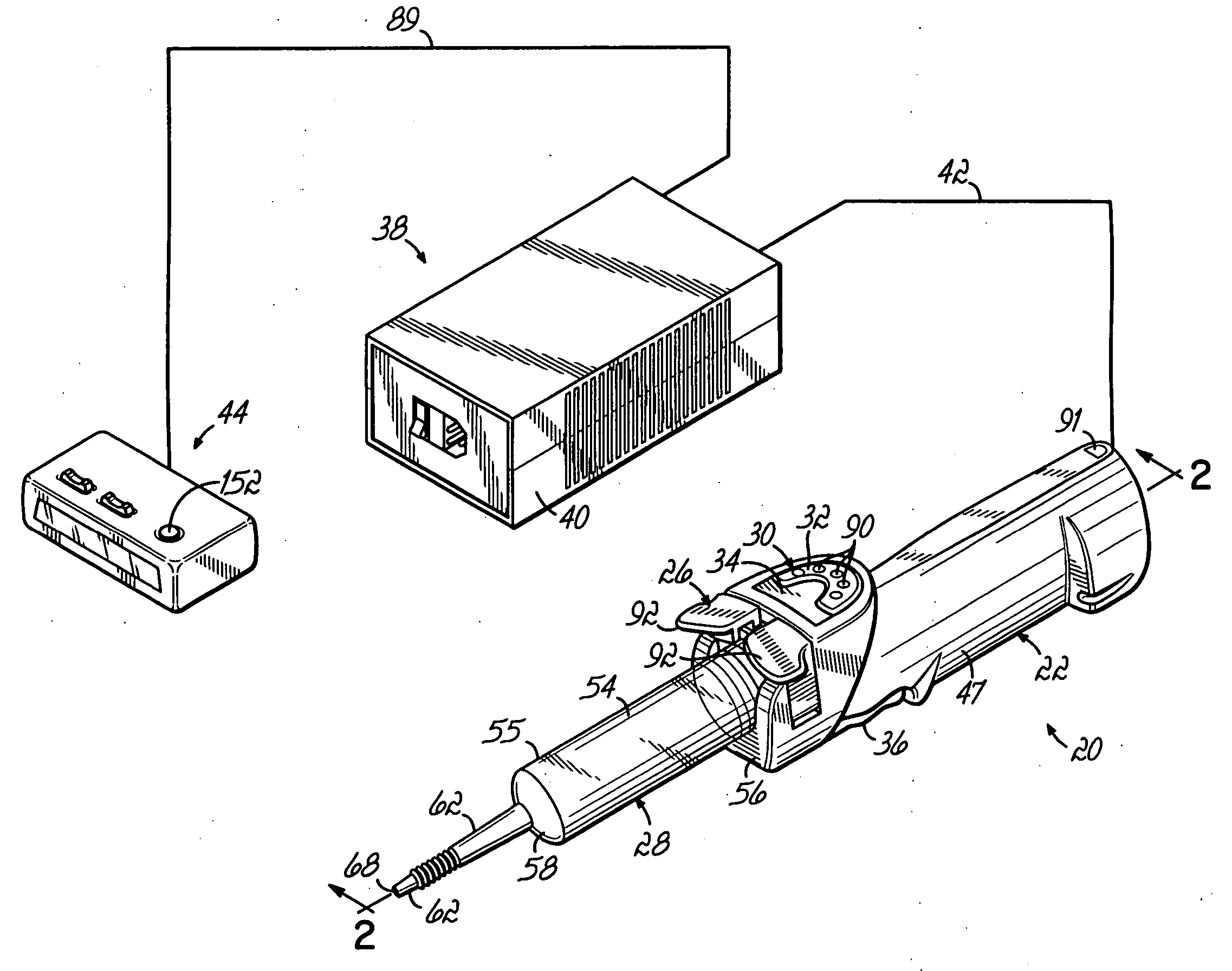
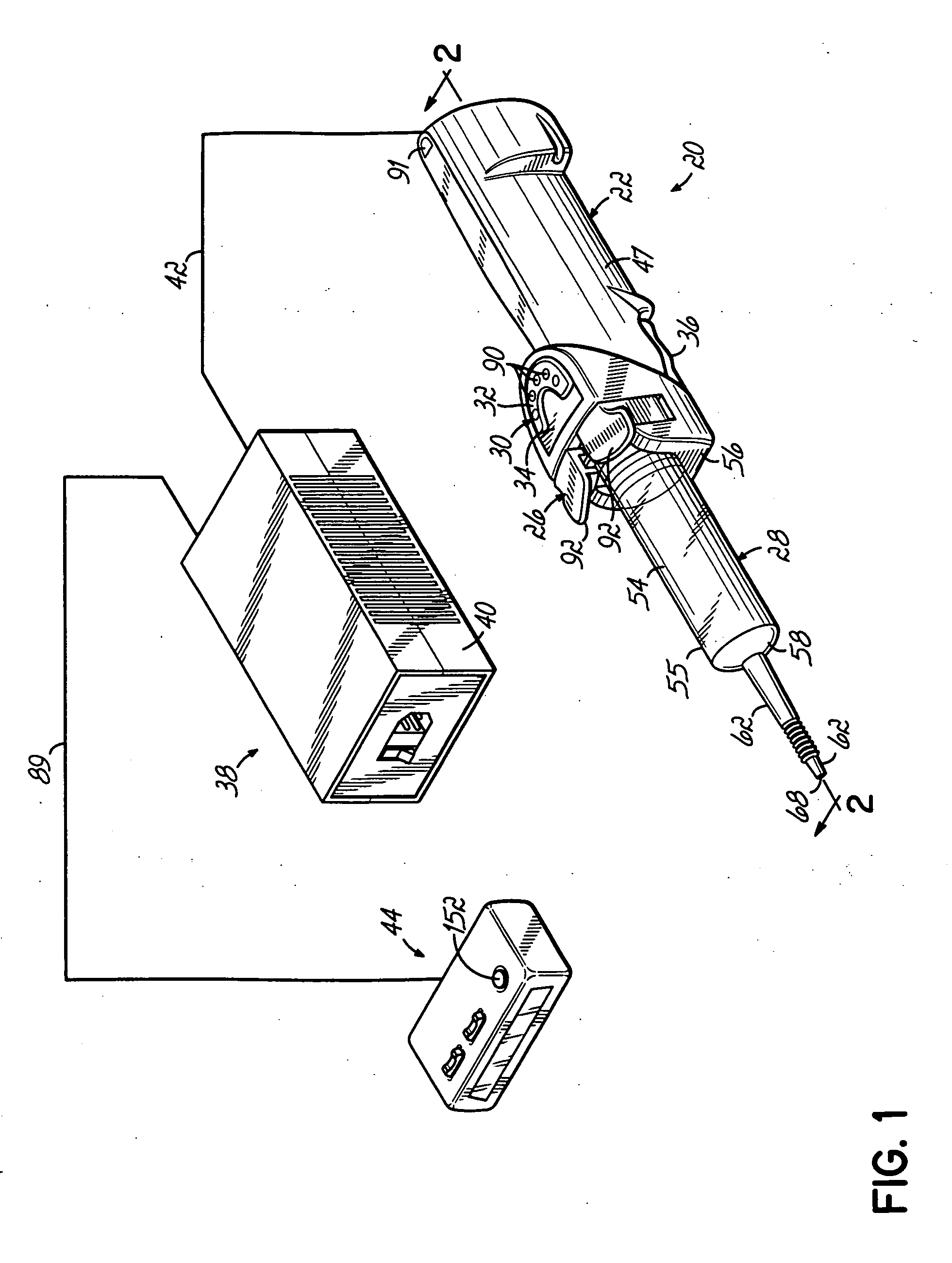
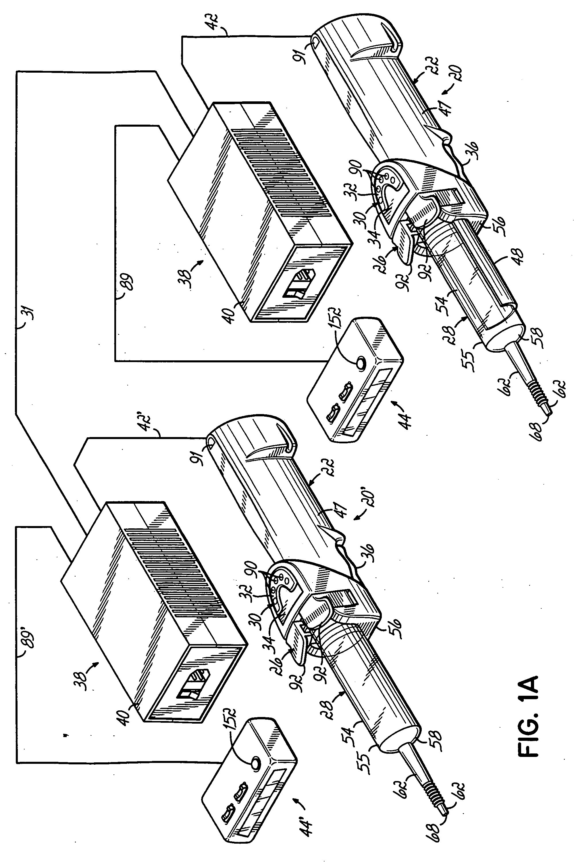
As described above in the summary of the invention, the present invention provides an injector which overcomes and eliminates the drawbacks of injectors as described above. With reference to the Figures, an injector 20 of the illustrated embodiment of the present invention may be provided in a “wand” shape in order to be hand held. The injector 20 of the present invention is designed to meet ordinary needs of the medical market and is therefore less expensive, smaller, and less complicated to operate. Features such as stored protocols, multi-phasic injections, high flow rate, and optional printer may be omitted in order to reduce costs and simplify the user-injector interface 30. With an optional injector-injector interface 31 (FIG. 1A), the injector 20 of the present invention may be joined with other compatible injectors in order to deliver greater volume injections, or a flushing solution (normally saline) in a similar manner as some other injection systems such as the Optistar ...


PUM


Abstract

An injector 20 that may be used to deliver radiographic contrast media and / or flushing solution into a patient's vascular system for the purposes such as obtaining enhanced diagnostic x-ray images. The injector includes the following features: (1) a syringe mount 26 for attachment of a syringe 28 to the injector 20; (2) display 34 and controls 90 for volume and flow rates; (3) automatic limiting of the operating pressure of the injector 20 as determined by the selection of a flow rate; (4) a syringe cradle 48 having a warming capability; (5) a purge / retract trigger 36 for control of the injection procedure having intuitive direction (i.e., forward for injecting, reverse for filing), non-contact control transmission through the housing of an injector 20 for an improved seal integrity, a speed lock, and / or the ability to change the concentration and / or flow rate of media or other fluid during an injection procedure; (6) a switch to determine when the drive ram 46 is in a “home” position; (7) a “soft” on / off power switch separate from the injector; and (8) a structure to prevent rotation of the drive ram 46 about its axis of symmetry 76. Additionally, the injector system includes software for the control of various components.

Description

FIELD OF INVENTION The present invention relates to injectors for injecting fluid into animal subjects, including humans. BACKGROUND OF THE INVENTION During many medical procedures, various fluids are injected into patients for purposes of diagnosis or treatment. An example of one such fluid is contrast media used to enhance angiography or CT imaging. Such fluids may also be used in other modalities, such as intravenous pyelogram (IVP) and cardiology. The injectors used in these procedures are often automated devices that expel the fluid from a syringe, through a tube, and into the subject. Injectors suitable for these applications generally include relatively large volume syringes and are capable of producing relatively large flow rates and injection pressures. For these reasons, injectors for such applications typically include large, high mass injection motors and drive trains. These are typically housed in an injection head, which is supported by a floor, wall, or ceiling mou...

Claims


Application Information

Patent Timeline
Patent Type & Authority Applications(United States)
IPC IPC(8): A61M5/00A61M5/14A61M5/145A61M5/168A61M5/172A61M5/44
CPCA61M5/007A61B6/548A61M5/14566A61M5/1458A61M5/16827A61M5/172A61M5/445A61M2005/1402A61M2005/1403A61M2005/14553A61M2205/3317A61M2205/3331A61M2205/3561A61M2205/3569A61M2205/3653A61M2205/702A61M5/31525A61M5/14546Y02A90/10A61M5/178A61M5/20
Inventor FAGO, FRANK M.NEER, CHARLESGIBBS, JONATHON D.
Owner LIEBEL FLARSHEIM CO
Learn More