Lubricating structure for an engine

a technology of lubricating structure and engine, which is applied in the direction of machine/engine, mechanical apparatus, auxiliaries, etc., can solve the problems of increasing the number of parts and difficulty in assembly of the conventional lubricating structure of the engine, and achieves the improvement of assembly ease, the effect of increasing the width of the engine and reducing the number of parts

Inactive Publication Date: 2005-02-24
HONDA MOTOR CO LTD
View PDF3 Cites 18 Cited by
  • Summary
  • Abstract
  • Description
  • Claims
  • Application Information

AI Technical Summary

Benefits of technology

[0009] According to the first aspect of the present invention, the oil suction path for introducing the oil in the oil reservoir into the oil pump is formed by coupling the pair of case halves to each other along the mating plane to form the crankcase. Therefore, when the lubricating structure for an engine is compared with a conventional lubricating structure for an engine which uses an oil pipe, increased width of the engine caused by leftward and rightward projection of the oil path can be prevented and a bank angle is assured. Further, the number of parts can be reduced and improvement in the ease of assembly can be achieved.

Problems solved by technology

Therefore, not only do the number of parts increase, but the conventional lubricating structure for an engine is not easy to assemble since it is necessary to attach the oil pump to the crankcase.

Method used


Image

  • Lubricating structure for an engine
  • Lubricating structure for an engine
  • Lubricating structure for an engine

Examples


Embodiment Construction

[0020] In the following, an embodiment of the present invention is described in connection with a working example of the present invention shown in the accompanying drawings.

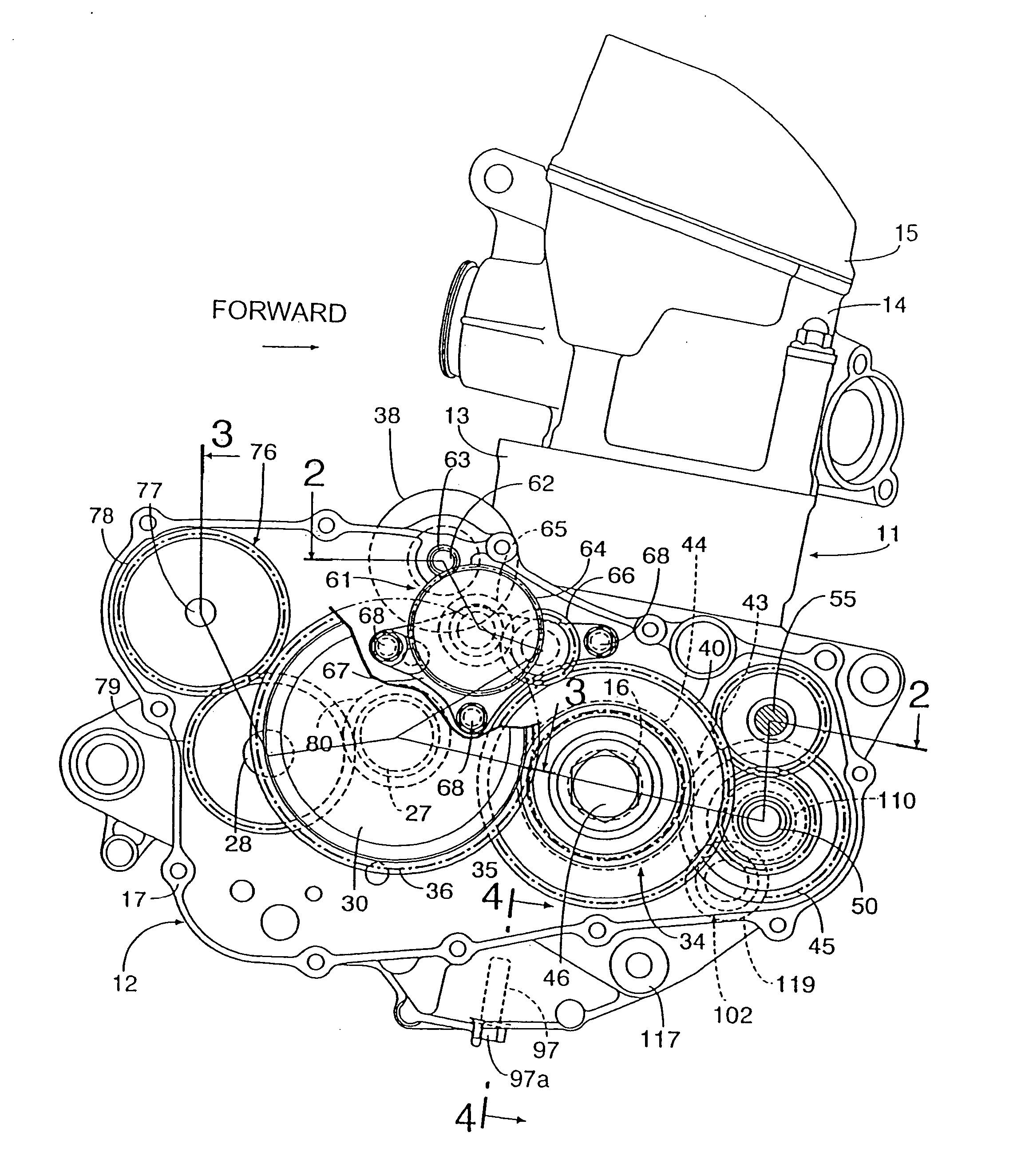
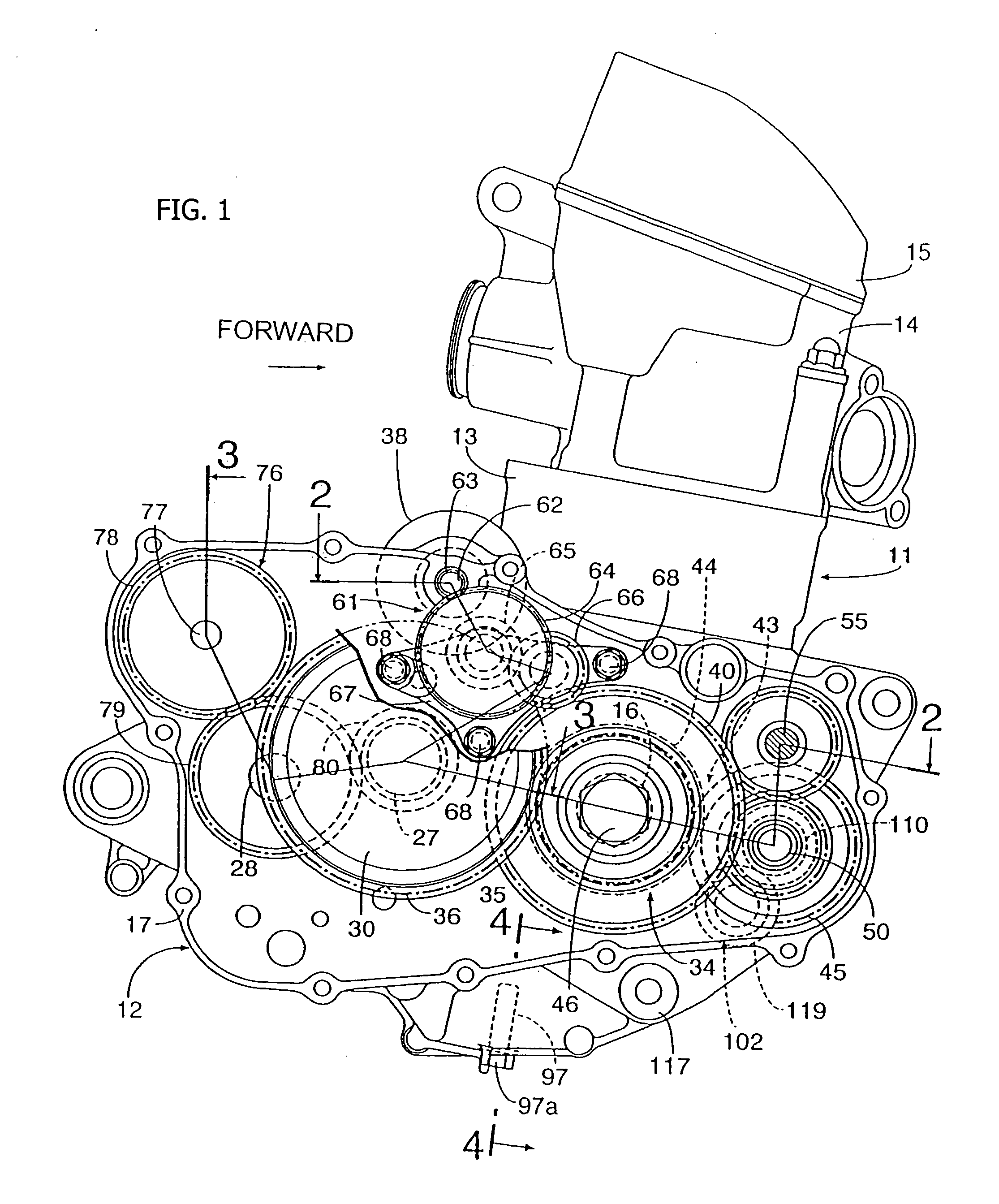
[0021] Referring first to FIG. 1, the engine is a single-cylinder 4-cycle engine incorporated in a vehicle such as a motorcycle. An engine body 11 includes a crankcase 12, a cylinder block 13 coupled to the crankcase 12, a cylinder head 14 coupled to the cylinder block 13, and a head cover 15 coupled to the cylinder head 14.

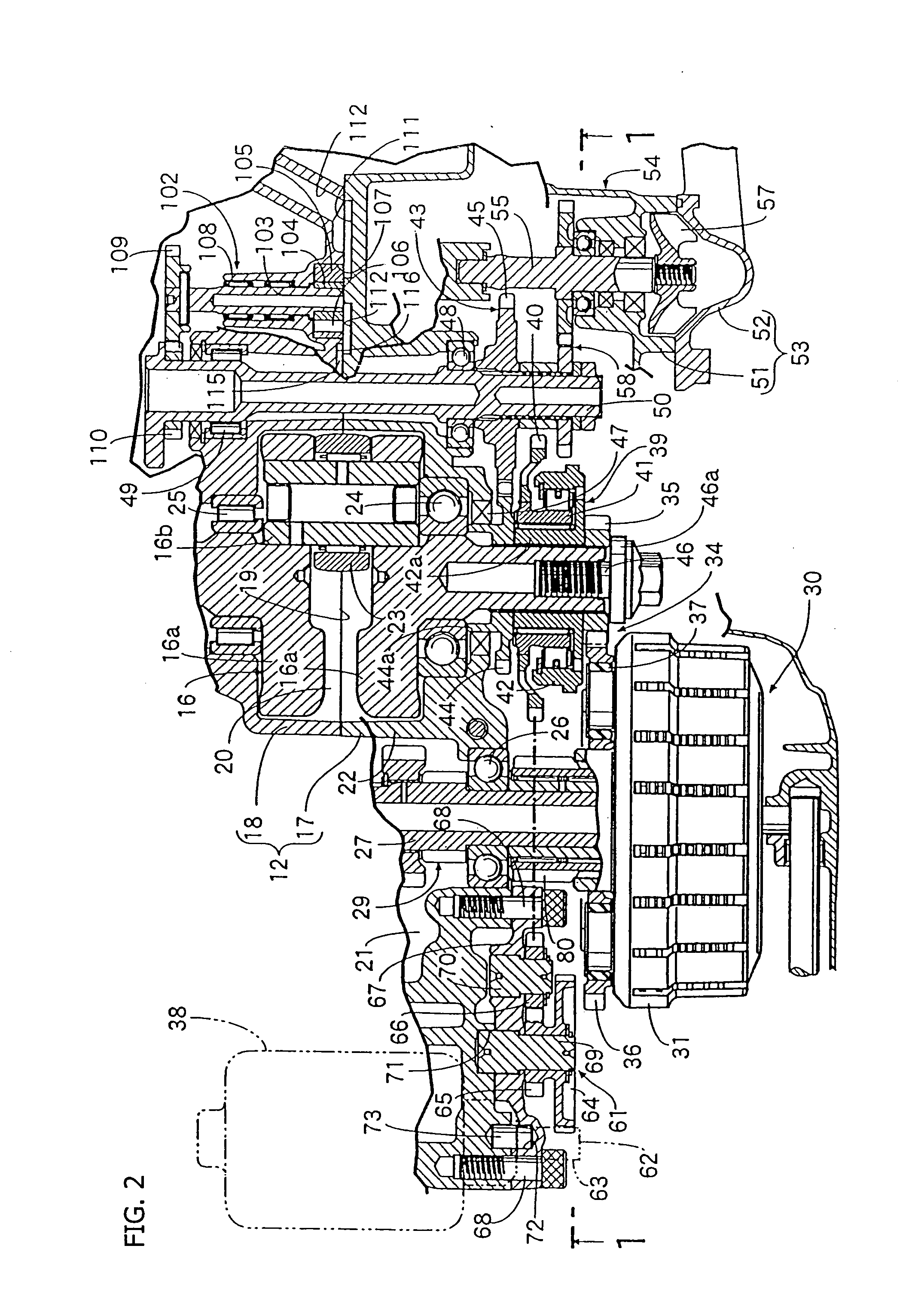
[0022] Referring also to FIG. 2, the crankcase 12 supports a crankshaft 16 for rotation thereon and includes a right case half 17 disposed on the right side when the crankcase 12 is incorporated in the motorcycle and a left case half 18 disposed on the left side when the crankcase 12 is incorporated in the motorcycle. The right case half 17 and the left case half 18 are coupled to each other along a mating plane 19 extending along a plane perpendicular to an axial line of the crankshaft 16....


PUM


Abstract

A lubricating structure for an engine includes a crankcase for supporting a crankshaft formed from a pair of case halves coupled to each other along a mating plane extending along a plane perpendicular to an axial line of the crankshaft. An oil reservoir in a lower portion of the crankcase extends across the mating plane. A pump chamber of an oil pump is formed between the two case halves across the mating plane. Lubricant is drawn from the oil reservoir into the oil pump using a structure which can achieve reduction of the number of parts and improve the ease of assembly. The structure includes a path groove, which forms an oil suction path for interconnecting the oil pump and the oil reservoir, formed in at least one of the two case halves.

Description

CROSS-REFERENCE TO RELATED APPLICATIONS [0001] The present invention claims priority under 35 USC 119 based on Japanese patent application No. 2003-296297, filed Aug. 20, 2003. 1. FIELD OF THE INVENTION [0002] This invention relates to a lubricating structure for an engine wherein a crankcase for supporting a crankshaft for rotation thereon is formed from a pair of case halves coupled to each other along a mating plane extending along a plane perpendicular to an axial line of the crankshaft and an oil reservoir is formed at a lower portion of the crankcase below the crankshaft in such a manner as to extend across the mating plane while a pump chamber of an oil pump for sucking oil from the oil reservoir is formed between the two case halves across the mating plane. 2. DESCRIPTION OF THE BACKGROUND ART [0003] A lubricating structure for an engine wherein an oil reservoir is formed between lower portions of a pair of case halves coupled to each other along a mating plane to form a cra...

Claims


Application Information

Patent Timeline
Patent Type & Authority Applications(United States)
IPC IPC(8): F01M1/06F01M1/02F01M11/00F01M11/04F02B61/02F02F7/00
CPCF01M1/02F01M11/0004F01M11/0408F02B61/02F01M2011/0037F01M2011/0066F01M2001/0284
Inventor TSUTSUMI, KOICHITAKAMATSU, HIDETOSHIABE, RYUICHISUGIURA, HIROYUKI
Owner HONDA MOTOR CO LTD
Why Eureka
Try Eureka