Impulse valve structure of apparatus for suppling inert gas alternately

Inactive Publication Date: 2005-02-24
KR PRECISION CO LTD
View PDF9 Cites 4 Cited by
  • Summary
  • Abstract
  • Description
  • Claims
  • Application Information

AI Technical Summary

Benefits of technology

[0077] Moreover, the inventive apparatus for an alternate supply of inert gases can minimize the occurrence of the crack and the breaking of the weld zone, and results in the uniform vertical sectional surface of the weld junction.
[0078] Particularly, according to the present invention, the problem of generation of the noise due to the vibration of the gas opening/closing device and pressure drop during the flowing of gas through the impulse valve, that the prior art apparatus for an alternate supply of inert gases has, is remarkably improved.
[0079] Namely, in case of the impulse valve structure according to the present invention, because the first and the second gas inlets and the gas outlet directly communicate each other, the pressure drop is prevented in the course of su

Problems solved by technology

However, in the weld zone 8a produced by conventional inert gas arc welding using only homogeneous single gas medium, such as pure helium or argon, very coarse cracks are found at several portions of a weld zone 8a.
In addition to the breaking, the base metal has a problem that conditions of the surface thereof are different according to a kind of inert gas.
For example, in case tha

Method used


Image

  • Impulse valve structure of apparatus for suppling inert gas alternately
  • Impulse valve structure of apparatus for suppling inert gas alternately
  • Impulse valve structure of apparatus for suppling inert gas alternately

Examples


Example

[0094] Preferred embodiment of an impulse valve structure of an apparatus for alternately supplying inert gases according to the present invention will be described below in detail with reference to accompanying drawings.

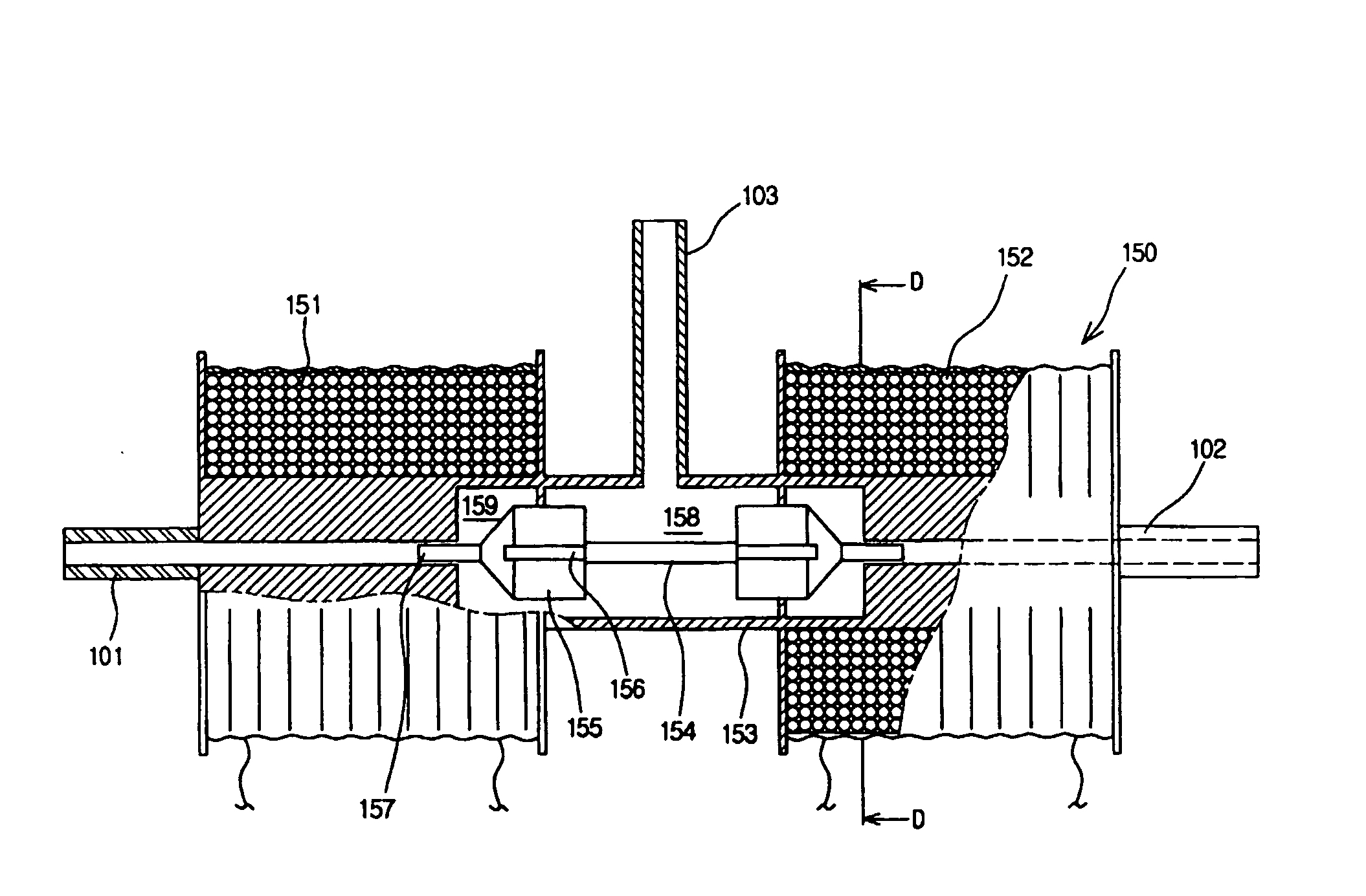
[0095]FIG. 9 is a cross-sectional view showing an impulse valve structure of an apparatus for alternately supplying inert gases according to the present invention, and FIG. 10 is a side view showing an impulse valve structure of an apparatus for alternately supplying inert gases according to the present invention.

[0096] FIGS. 11 to 13 sequentially show operation states of an impulse valve of an apparatus for alternately supplying inert gases according to the present invention.

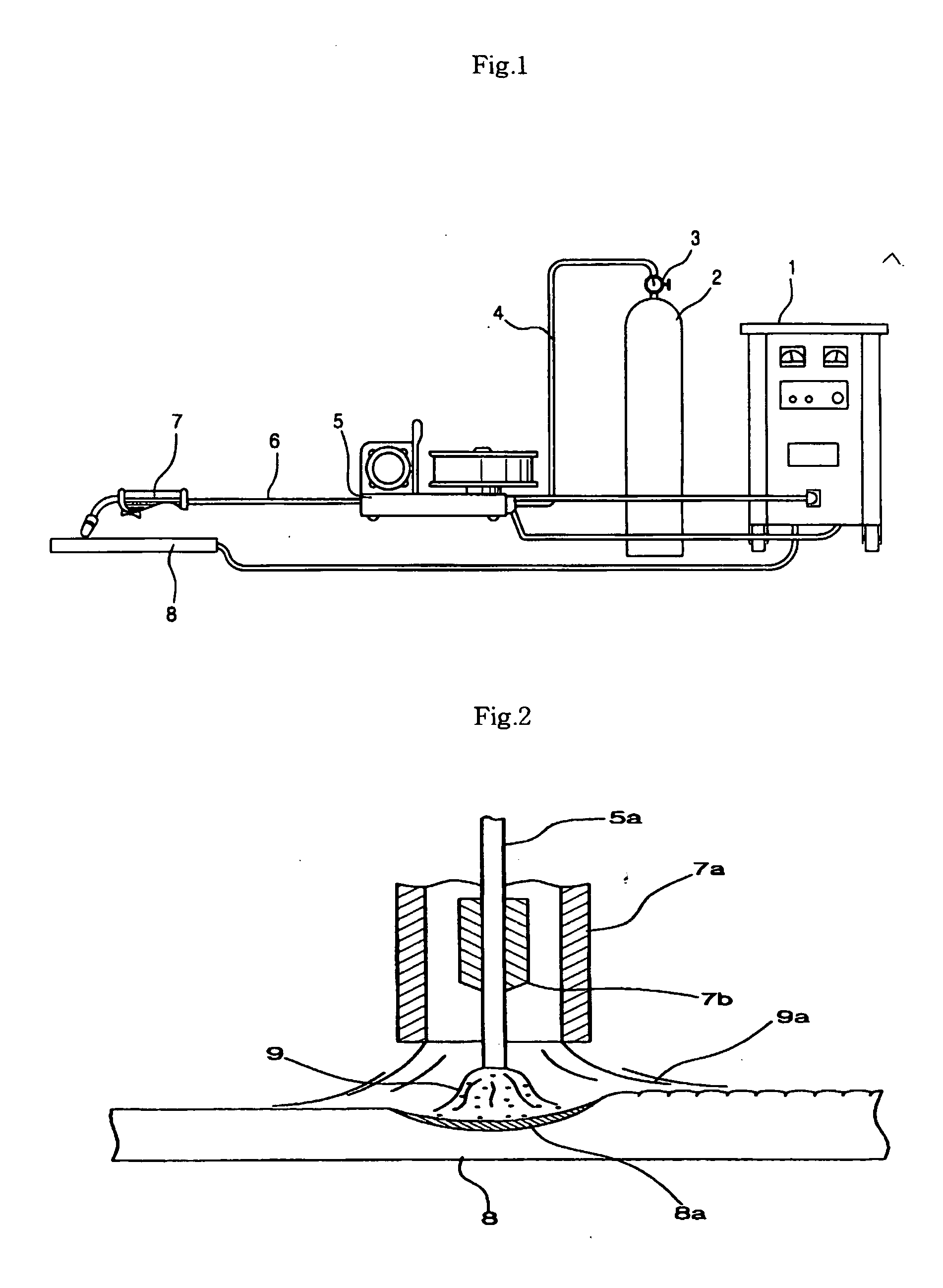
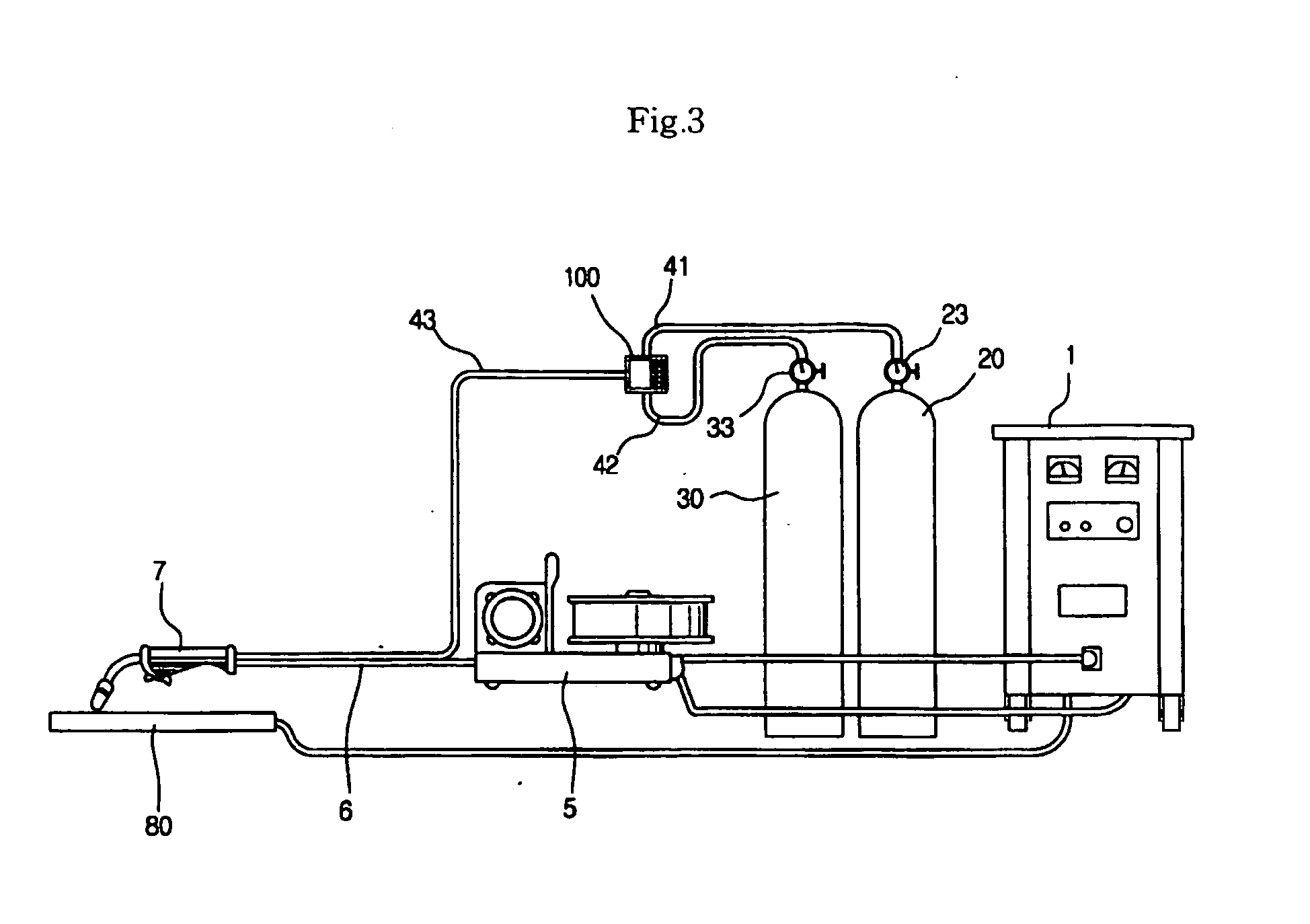
[0097] Here, in the explanation of an impulse valve structure according to the present invention, an apparatus for alternately supplying inert gases described as a prior art will be cited when the explanation thereof is necessary, because the general constitution of an apparatus for alternat...


PUM

PropertyMeasurementUnit
Lengthaaaaaaaaaa
Pressureaaaaaaaaaa
Diameteraaaaaaaaaa

Abstract

The present invention relates to an impulse valve structure which can prevent the pressure drop within the impulse valve and the vibration of a spool when inert gases are supplied alternately. The impulse valve structure comprises: a hollow body (210) having a first and a second gas inlets (211, 212) and a gas outlet (213); a spool (220) inserted into the inside of the hollow body (210) to partition a first and a second gas chambers (261, 262) and to alternately discharge the inert gases by means of straight reciprocal movement; a plurality of plunger guides (240) connected on the opposite ends peripheral surfaces of the hollow body (210) for securing a stopper (230); and a first and a second solenoids (251, 252) disposed on the peripheral surfaces of the plunger guide (240) for providing the magnetic force enabling the straight reciprocal movement of the spool (220).

Description

TECHNICAL FIELD OF THE INVENTION [0001] The present invention relates to an impulse valve structure of an apparatus for supplying inert gas alternately, more particularly, to the impulse valve structure which can prevent the pressure drop within the impulse valve and the vibration of a spool when inert gases are supplied alternately, by changing the structure of the impulse valve, and has fins for efficiently radiate the heat generated from solenoid coils. BACKGROUND OF THE INVENTION [0002] In general, an inert gas tungsten arc welding (TIG) suitable for welding base metals having thickness ranging from 0.6 mm to 3 mm and an inert gas metal arc welding (MIG) for welding base metals having thickness of 3 mm or higher have been widely used as an inert gas arc welding. [0003] Such inert gas arc welding in which an electric arc is generated between the base metals and a tungsten rod or a metal wire electrode under an atmosphere of the inert gas which has been known to show no reaction w...

Claims


Application Information

Patent Timeline
IPC IPC(8): F16K31/06B23K9/16
CPCF16K31/0613F16K31/0679F16K31/0627Y10T137/86879B23K9/16
Inventor KIM, WOONG KI
Owner KR PRECISION CO LTD
Why Eureka
Try Eureka