
Apparatus for connecting planar plastic materials

Inactive Publication Date: 2005-02-24
LEISTER PROCESS TECH
View PDF20 Cites 16 Cited by
  • Summary
  • Abstract
  • Description
  • Claims
  • Application Information

AI Technical Summary

Benefits of technology

[0007] According to a further preferred design, passages for injecting air for mounting the roller are arranged in the processing head. This ensures a good rotary movement of the roller in the processing head.
[0010] In order to minimize the installation space, the processing head can be coupled to a light fiber without focussing devices. The resulting focus point restricts the maximum welding speed. This disadvantage can be compensated for by increasing the number of individual processing heads and thus by higher production efficiency.
[0013] In principle, it is also possible to heat the rest surface of the component of large area to be welded or also the cylinder so that the plastic strips are heated before the welding process in order to improve the quality of thermal contact.

Problems solved by technology

In principle, however, it is also possible for this application to use glass balls instead, the latter being more complicated, since the welding lines or seams are thus always further apart than when using a transparent roller or disk.

Method used


Image

  • Apparatus for connecting planar plastic materials
  • Apparatus for connecting planar plastic materials
  • Apparatus for connecting planar plastic materials

Examples


Embodiment Construction

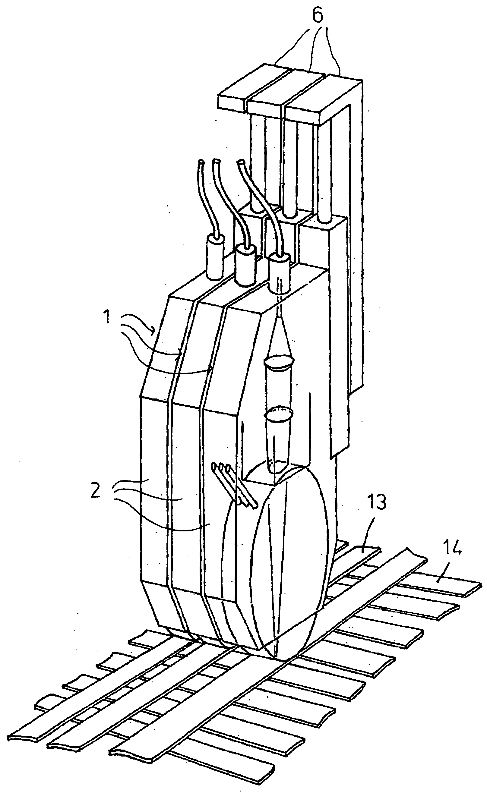
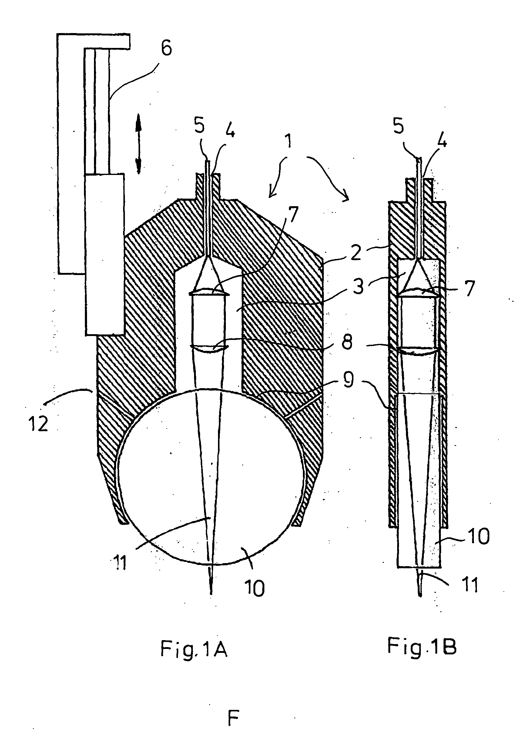
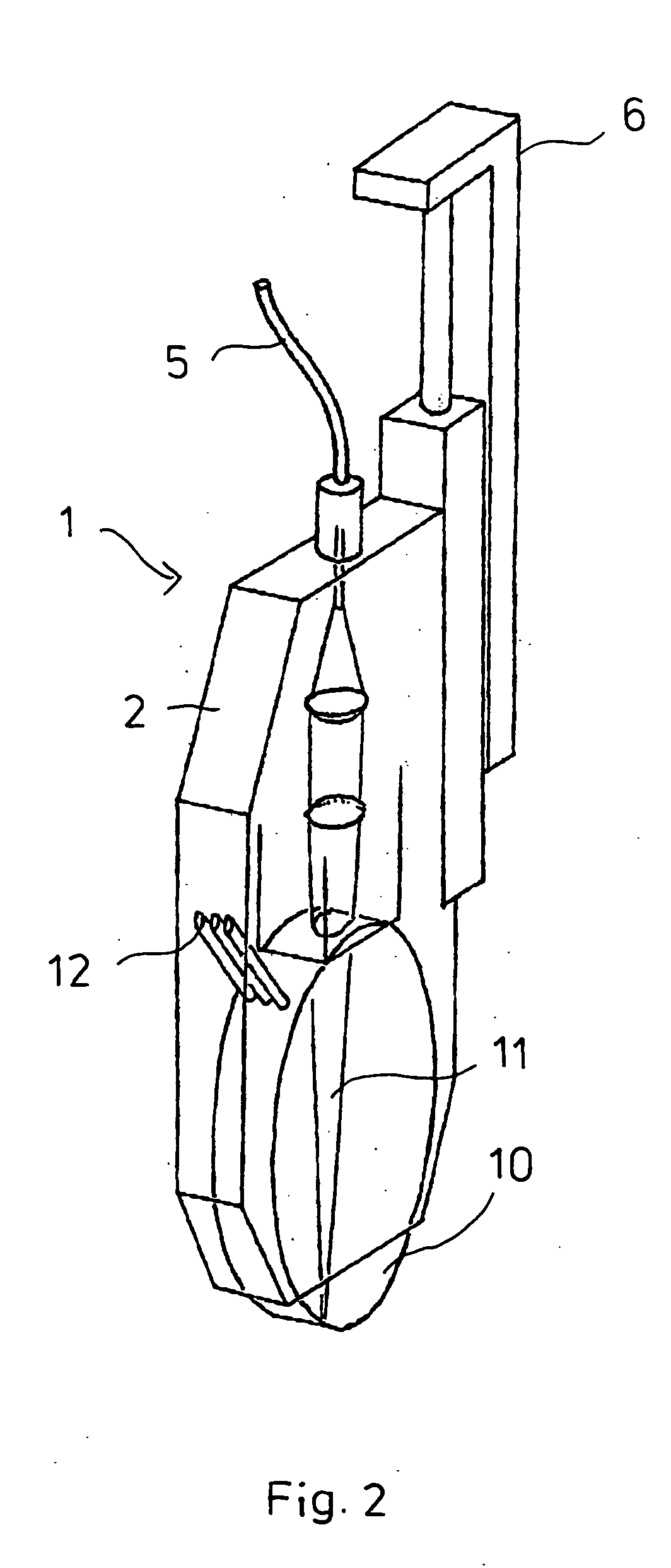
[0021]FIG. 1 shows the processing head 1 having a housing 2 which is mounted on a frame (not shown) such as to be movable in the vertical direction by means of a pneumatic piston / cylinder unit 6. The laser beam is introduced into the interior of the housing 2 into a cavity 3 via a light fiber 5 which lies in a bore 4. Correspondingly suitable lenses 7 for forming the laser beam 11 coupled via the light fiber 5 are located in the cavity. Following the cavity 3 is a second cavity 9 for accommodating a disk-shaped glass roller 10, through which the laser beam 11 passes and which is likewise included during the focussing of the laser beam 11 on the desired focus plane. For mounting the disk-shaped glass roller 10, passages 12 for introducing compressed air are provided in the housing.

[0022] From the representation according to FIG. 1B, it can be seen that the processing head is determined with regard to its width by the maximum width of the optical elements 7, 8 and the disk-shaped gla...


PUM

PropertyMeasurementUnit
Pressureaaaaaaaaaa
Areaaaaaaaaaaa
Transparencyaaaaaaaaaa

Abstract

An apparatus for welding over a large area according to the laser transmission method, in particular for welding plastic strips to form a grid structure. To this end, a multiplicity of processing heads are assembled to form a unit, so that a high production throughput can be achieved. Spacer devices for setting the distance of the top transparent material strips to be welded are also located between the individual processing heads.

Description

BACKGROUND OF THE INVENTION [0001] The present invention relates to an apparatus for connecting planar plastic materials according to the laser transmission method, in which a top material layer which faces a laser source and is transparent for the laser beam is connected under the application of pressure to a bottom layer which is absorbent for the laser beam, having a processing head for accommodating guide devices for the laser beam and a device for transmitting the laser beam under the application of pressure to the materials to be connected. [0002] This method of plastic welding with a laser beam is generally known and is also referred to as transmission welding. For this plastic welding method, it is important that the materials are restrained with one another during the welding operation, since an important precondition for a good welded connection of the materials by means of laser radiation is not only the dosage of energy but also the neat mechanical contact between the tw...

Claims


Application Information

Patent Timeline
IPC IPC(8): B23K26/20B23K26/00B23K26/32B29C65/00B29C65/16
CPCB29C65/1635B29C65/1674B29C66/1122B29C66/232B29C66/3452B29C66/43B29C66/81267B29C66/81469B29C66/8161B29C66/8242B29C66/83441B29C66/8362B29C66/8432B29C66/86535B29K2909/08B29L2028/00B29C66/0242B29C66/86533B29C65/1658B29C65/1664B29C66/024B29C66/73921B29C66/8122B29K2995/0027
Inventor CHEN, JIE-WEIPIRONATO, MARCEL
Owner LEISTER PROCESS TECH
Learn More